TB XRN2 02.00 E
27
7
Relay testing and
commissioning
The following test instructions should help to verify the
protection relay performance before or during commis-
sioning of the protection system. To avoid a relay
damage and to ensure a correct relay operation, be
sure that:
•
the auxiliary power supply rating corresponds to the
auxiliary voltage on site.
•
the rated frequency and rated voltage of the relay
correspond to the plant data on site.
•
the voltage transformer circuits are connected to the
relay correctly.
•
all signal circuits and output relay circuits are con-
nected correctly.
7.1
Power-On
NOTE!
Prior to switch on the auxiliary power supply, be sure
that the auxiliary supply voltage corresponds to the
rated data on the type plate.
Switch on the auxiliary power supply to the relay and
check that the message "ISEG" appears on the display
and the self supervision alarm relay (watchdog) is en-
ergized (terminals 71 and 74 closed).
It may happen that the relay is tripped because of un-
der voltage condition after power-on. (The message
"TRIP" on the display and LED L1, L2, L3 and U< light
up red). An undervoltage condition has been detected
after power-on, because no input voltages are applied
to the relay. In this case:
•
Press the push button <ENTER>, thus entering into the
setting mode. Now set the parameters U< and U<<
to "EXIT" to block the undervoltage functions. After
that, press the <SELECT/RESET> for app. 3 s to reset
the LEDs and "TRIP" message.
•
The undervoltage tripping after power on can also
be eliminated by applying three phase rated voltages
after power-on and reset the LED and "TRIP" message.
•
Apply auxiliary voltage to the external blocking input
(Terminals C1/C1L or C1/C1H) to inhibit the un-
dervoltage functions (refer to 6.2.10) and press the
<SELECT/RESET> for app. 3 s to reset the LEDs and
"TRIP" message.
7.2
Testing the output relays
NOTE!
Prior to commencing this test, interrupt the trip circuit to
the circuit breaker if tripping is not desired.
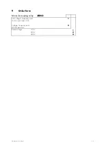
By pressing the push button <TRIP> once, the display
shows the first part of the software version of the relay
(e.g. „D08-“). By pressing the push button <TRIP>
twice, the display shows the second part of the soft-
ware version of the relay (e.g. „4.01“. The software
version should be quoted in all correspondence. Press-
ing the <TRIP> button once more, the display shows
"PSW?". Please enter the correct password to proceed
with the test. The message "TRI?" will follow. Confirm
this message by pressing the push button <TRIP> again.
All output relays should then be activated and the self
supervision alarm relay (watchdog) be deenergized
one after another with a time interval of 1 second.
Thereafter, reset all output relays back to their normal
positions by pressing the push button
<SELECT/RESET>.
7.3
Checking the set values
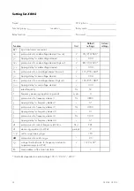
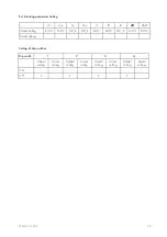
By repeatedly pressing the push button <SELECT>, all
relay set values may be checked. Set value modifica-
tion can be done with the push button <+><-> and
<ENTER>.
As relay input energizing quantities, three phase volt-
ages should be applied to
XRN2
relay input circuits.
Depending on the system conditions and the voltage
transformer used, three voltages can be connected to
the relay input circuits with either star or delta connec-
tion. In case of a star connection the phase-to-neutral
voltage will be applied to the voltage input circuits,
while the phase-to-phase voltages will be connected to
the voltage input circuits in case of a delta connection.
The voltage input connection must be set as a parame-
ter, and should correspond with the actual voltage in-
put connection:
Star connection: Phase-to-neutral voltages will be
measured and evaluated.
Delta connection: Phase-to-phase voltages will be
measured and evaluated.
Содержание XRN2
Страница 1: ...XRN2 Mains decoupling relay ...
Страница 40: ...40 TB XRN2 02 00 E ...


