10
|
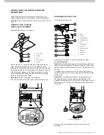
EZQ MODEL VARIATION
ILL1228-F
A Solenoid
B Nut & Gland (connects to float valve)
C Nut (connects flexible hose to Soleniod)
D Tube Assy (solenoid to float valve)
E Nut (connects Solenoid to tube assy)
F
Flexible hose assy
G Solenoid cover
H Solenoid power leads
I
Float Valve Nipple
F
E
D
H
I
C
B
A
ILL1102-E
ILL1147-C
A Nut (connects Flexible hose
to Solenoid).
B Nut (connects Solenoid to
elbow).
C Nut (connects to Float Valve).
D Flexible Hose and elbow assy.
Note!
Solenoid barrel must face towards front so
terminals face upwards
E Solenoid.
F Elbow (Solenoid to Float Valve).
G Solenoid cover.
H Solenoid connection cable.
I
Float Valve connection
(connect
nut “C”)
INSTALLING THE INLET SOLENOID
For coolers fitted with a drain and solenoid valve, it is a
requirement to fit the new detachable hose set supplied.
Any old hose sets should not be re-used.
For EXQ/EXS model coolers, fit the inlet solenoid under the
tank as shown:
Ensure washers are correctly located. Do not over tighten
plastic fittings.
Insert the solenoid cable through the hole in the cooler tank
(behind the drain valve) and connect to the water solenoid
valve. Make sure the cable is fitted to the groove underneath
the tank so it does not get trapped by the solenoid cover when
fitted. The cable leads can be connected to the solenoid either
way around.
Important!
The cable must wrap underneath the solenoid.
Fitting the Solenoid Cover:
Once the solenoid valve and its cable has been fitted, place the
cover over the assembly. Make sure the solenoid valve cable is
retained in the groove in the cooler tank. Secure the cover by
tightening the flexible hose assembly nut (C).
Important!
Make sure the cable cannot lay in the water at any
stage. Connect the electrical leads to the solenoid.
The electrical cable leads may be connected to the solenoid
either way around.
Important!
If freezing conditions can occur at any time, a drain
down facility must be provided at the lowest point of the water
supply pipe.
Taps or shutoff valves used must not be of the non - return type.
Water drained from the cooler must be carried away to a
suitable discharge point in accordance with local regulations.
Important!
Make sure the cable cannot lay in the water at
any stage.
Connect the electrical leads to the solenoid. The electrical
cable leads can be fitted either way around.
Fitting the Solenoid Cover:
Once the solenoid valve and its cable have been fitted,
place the cover over the assembly. Ensure that the cover
does not touch the solenoid. Also make sure the solenoid
valve cable is retained in the groove in the cooler tank.
Then secure the cover at each end, with the two screws
supplied.
Important!
If freezing conditions can occur at any time, a
drain down facility must be provided at the lowest point of
the water supply pipe.
Taps or shutoff valves used must not be of the non-return
type.
Fit the inlet solenoid under the tank as shown.
Release the coiled up solenoid cable then remove the
overflow cap. Pass the cable down and out of the overflow
pipe. Refit the cap, ensuring the cable is located in the
groove in the cap.

