12
|
Colour
Flash
Indicates
No glow
No power or a failure has occurred. (Check
power supply to cooler including isolating
switch, circuit breaker and plug and socket
connection in the roof space.)
Green
Every 2 sec
Normal Operation.
Red
1 Flash
Fault Code #1
Communication Failure.
2 Flash
Fault Code #2
Failure to Detect Water at Probes.
4 Flash
Fault Code #4
Failure to Clear Probes during drain.
Sal Flash
Indicates
OFF
Not Applicable
1 Flash
WaterMiser
®
salinity is below the set point.
2 Flash
WaterMiser
®
salinity is above the set point.
3 Flash
The Salinity Control Method is set for Timed Drain
4 Flash
The Salinity Control Method is set for Continuous Bleed.
(Bleed Funnel used)..
5 Flash
Thermostatic Control (no Water) operation set.
Continuously on
(When probes
immersed in water)
Water not detected. The probes are immersed in water
but are open circuit, or measured salinity is less than
20µs/cm (the water has very little salt content).
Continuously on -
(No water in tank)
WaterMiser
®
/ Drain Valve option is active
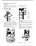
ILL1661-A
ILL1660-A
COMMISSIONING THE COOLER cont.
ILL1659-A
Refer to the installation manual provided with the MagIQtouch
controller for instructions on installing the controller.
Coolers are supplied with a 20m (66’) control cable. Longer
cable lengths are available from Seeley.
Important!
The maximum cable length allowed from the
MagIQtouch controller to the first cooler is 25 metres (82’). For
any additional coolers added into the system with a link module
the maximum allowed length is 40 metres (131’). Therefore,
failure of the product or components to operate correctly due
to modification to supplied cables, or the use of non-approved
cables will NOT be accepted under the Manufacturer’s
Warranty.
We have this cable available through our sales order office and
spare parts outlets in the following lengths:
Part No. Length Details
833880
20m
MagIQtouch Controller Cable (No Ferrite)
823553
20m
MagIQtouch Controller Cable (With Ferrite)
862873
1.5m
MagIQtouch Controller Cable (No Ferrite)
861265
3m
MagIQtouch Controller Cable (No Ferrite)
864396
30m
MagIQtouch Controller Cable (With Ferrite)
864402
40m
MagIQtouch Controller Cable (With Ferrite)
CONNECTING THE MAGIQTOUCH/
MAGIQCOOL CONTROLLER
®
Once the controller is connected, power up the cooler using the
ON/OFF switch on the cooler electronics box.
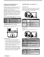
DIAGNOSTIC LED
Look at the front of the cooler electronics box where 2 LEDs are
situated on the right hand side. The top LED glows green or red
acting as a diagnostic indicator. If the top LED is double flashing
green, everything is OK, this is normal operation.
SALINITY LED
The bottom LED is red only and displays salinity setting
information.
IMPORTANT NOTES:
•
The cooler electronics box is a non-serviceable part.
Do not open or attempt to repair any components.
•
The cooler electronics box cover will only open and close
with the ON / OFF switch in the “OFF” position. Do not try
to force the cover open with the switch in the “ON” position.
•
Always turn “OFF” mains power to the cooler before
checking connections or touching wiring and components
connected to the cooler electronics box.
•
Take care to position the cables into the cover slots when
closing, so that they do not become caught or pinched.
•
The cooler electronics box is fitted with a 12A re-settable
circuit breaker. To reset the circuit breaker isolate power
from the cooler, and push the manual reset toggle switch
located on the base of the cooler electronics box.
COMMISSIONING THE COOLER
Sal Flash
Controller Salinity Setting
5 Flash
Salinity Control set
5 Flash
Timed Drain
4 Flash
The Salinity Control method is set for continuous bleed
(bleed tray used)
5 Flash
Thermostatic Control No Water
(no water) operation
Salinity LED Indication for evaporative coolers fitted with bleed
trays and shorting links only.

