11 Rev. 1.2 13/01/2021
Warning:
- When limit switches are connected to the control unit, the
detection of an obstacle always causes the motor to change
direction
during the closing phase, and also during the opening phase,
for 2 seconds.
- When no limit switches are connected to the control unit, the
detection of an obstacle always causes the motor to change
direction during the closing phase (except for the last 5
seconds of the operation when it performs a Stop) and to
change direction for 2 seconds during the opening phase
(except for the last 5 seconds of the operation when it
performs a Stop).
Deceleration:
The motor deceleration function is used on the gates to stop
the mobile doors from reaching their final position at a high
speed in the opening and closing phases.
During Motor Time programming, the control unit also programs
deceleration at desired points (before complete opening and
closing). Furthermore, by means of the VR1 “RAL” trimmer, it is
also possible to adjust the end force intensity during the
deceleration phase.
If you are using the “Automatic programming” function (see the
main menu), it is also possible to disable the deceleration
phase (see Configuration Menu
C7
).
Warning light :
The centre allows the connection of a (12) 24Vdc
3 W max. to show the state of the automation process. Light:
off, automation closed; on, open; slow flashing, opening
motion; fast flashing, closing motion.
Flashing Light or Courtesy Light function:
The control unit is equipped with an output to manage a (12)
24Vdc 4W max flashing light. Its operation is conditioned by the
settings selected in the “ Menù C “.
Electric Lock Control Output:
The control unit has an output to control the electric locks (12)
24 Vdc 12W max. The control is activated with every initial
opening movement and lasts 2 sec.
Buffer Battery:
The control unit is provided with an incorporated battery
charger that enables connection to a (12) 24 V buffer battery
having a max. capacity of 7Ah, which will execute
approximately 20 complete manoeuvres.
The Flashing light, if applicable, will only function for the first 4
seconds of the manoeuvre in the event of no power supply.
Solar Panel:
The control unit enables connection of a Solar Panel for the
emergency battery charger.
Operation with TIMER:
The control unit can have a timer set up instead of an open-
close ( PUL ) control button.
Example: at 08:00 the timer closes the contact and the control
unit opens the gate. At 18:00 the timer opens the contact and
the control unit closes the gate. During the interval between
08:00 and 18:00, at the end of the opening phase, the control
unit disables the flashing beacon, automatic closing and radio
controls.
S
ELECTION AND
C
ONFIGURATION
K
EYS
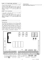
The control unit is provided with a Selection ( SEL ) and
Confirmation ( SET ) button, a comprehensive 2-Digit DOT
Display to view the selected settings.
DIGIT 1
– DIGIT 2 :
function display.
DOT 1 :
“Flashing” function selected while on standby for
modifications.
DOT 2 :
“ ON/OFF ” function status enabled or disabled.
SEL button :
forward scrolling of the Programming menu
Display to view the function to select.
Once the function is selected by pressing SET, the selection
remains active for 20 seconds and is displayed by the selected
function. After 20 seconds, the control unit goes back to its
original status “ ( - - ) Power On”.
SET button:
selection of the selected function to view the
status. Furthermore, pressing the SET button again while DOT
1 is flashing will change the status
(therefore operation) of the selected function with DOT 2 going
on or off. After 20 seconds, the control unit goes back to its
original status “( - - ) Power On”.
C
ONFIGURATIONS
M
ENU
:
DISPLAY
SELECTIONS LIST
A (1-9 )
Menu A
B ( 1-9 )
Menu B
C ( 1-9 )
Menu C
RS
Reset default settings
RC
Deletion of the memorised radio-controls
RT
Reset default time settings
PS
Enter Password from 0 to 99
ST
Software Revision
M
ESSAGES
M
ENU
:
DISPLAY
MESSAGES LIST
AF
Full Radio controls storage
AP
Radio control already present in memory
AR
Radio control not recognised
TP
Failed Photocell Test
EE
General fault
ER
General error
PS
Enter/delete Password.
-
-
Power On
DOT 1
DOT 1 Flashing light = Function selected
DOT 2
DOT 2 OFF/ON = OFF/ON function status


