


Section 04 ENGINE MANAGEMENT (1503 4-TEC)
Subsection 01 (OVERVIEW)
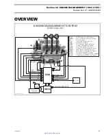
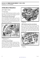
ENGINE MANAGEMENT
SYSTEM (EMS)
A highly advanced EMS has been used to ensure
a high power output with cleanest combustion.
The EMS calculates the proper air/fuel mixture and
ignition timing for each cylinder separately.
NOTE:
The EMS includes an ECM (engine control
module), MPEM (multi-purpose electronic mod-
ule), sensors, injectors, electromagnetic valves
and ignition components.
The EMS is controlled by its ECM (Engine Control
Module).
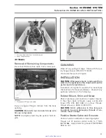
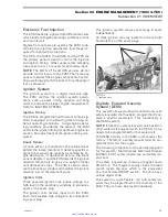
ECM (Engine Control Module)
1
R1503motr215A
TYPICAL
1. ECM
The ECM is mounted on the intake manifold. It
controls all engine management functions, by pro-
cessing the information given by various sensors.
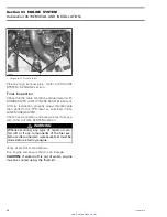
1
R1503motr214A
TYPICAL
1. ECM on intake manifold
The ECM gets its power by the MPEM which is di-
rectly powered by the battery. It is responsible for
the following engine management/electrical func-
tions:
– interpreting information
– distributing information
– start/stop function
– DESS (Digitally Encoded Security System)
– ignition timing control
– injection control
– engine RPM limiter
– etc.
The ECM applies the proper map (injection and ig-
nition) for optimum engine operation in all condi-
tions.
The ECM also stores the fault codes and gener-
al information such as: operating conditions, ve-
hicle hours, serial numbers, customer and main-
tenance information. The ECM features a perma-
nent memory that will keep these informations,
even when the battery is removed from the wa-
tercraft.
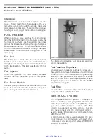
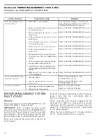
Multi-Purpose Electronic Module
(MPEM)
The MPEM distributes power from battery to all
accessories and the ECM. Accessories are pro-
tected by fuses integrated in the MPEM. Fuse rat-
ings is identified besides their holder.
72
smr2005-011
www.SeaDooManuals.net


