


Section 07 PROPULSION
Subsection 01 (JET PUMP)
Apply BOMBARDIER LUBE (P/N 293 600 016) on
the wear ring surface. Start screwing the impeller
on its shaft. If impeller is too tight, use the im-
peller shaft pusher (P/N 529 035 955) to turn im-
peller to machine wear ring before installing on ve-
hicle. Make sure to turn it smooth enough so that
engine starter should turn it.
Mount impeller remover/installer in a vise.
For
GTX
4-TEC,
Wake
and
GTX
4-TEC
Supercharged
models
,
use
the
impeller
remover/installer (P/N 529 035 820) and for the
GTX 4-TEC Limited, RXP and RXT models
, use
the impeller remover/installer (P/N 529 035 956).
Install partially screwed impeller on it.
Use a 12 mm Allen key to torque impeller shaft to
80 N•m (59 lbf•ft) then remove tool.
CAUTION:
Never use any impact wrench to
tighten impeller shaft.
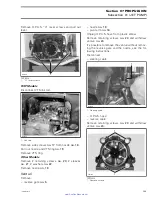
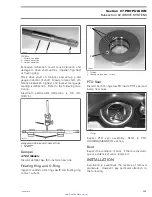
Apply 26 cc of jet pump bearing grease (P/N 293
550 032) in the impeller shaft area.
F18J17A
TYPICAL
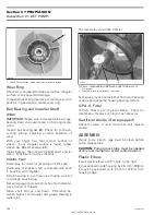
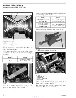
Put the rest of the jet pump bearing grease tube
in the impeller cover (approximately 80 cc).
F18J18A
TYPICAL
Install impeller cover with new self-locking
screws. Torque to 7.5 N•m (66 lbf•
in
). Push
cover against pump housing while tightening
screws.
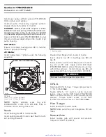
Venturi
If needed, install new O-rings
no. 42
around bailer
passages.
F00J0KA
1
1. O-rings
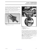
Position venturi
no. 24
with bailer passages on
top.
Apply Loctite 243 (blue) (P/N 293 800 060) on
threads of screws
no. 23
.
Install screws
no. 23
, lock washers and flat wash-
ers then torque to 21 N•m (16 lbf•ft).
198
smr2005-019
www.SeaDooManuals.net


