


Section 04 ENGINE MANAGEMENT (1503 4-TEC)
Subsection 03 (COMPONENT INSPECTION, REPLACEMENT AND ADJUSTMENT)
Tighten jam nut and recheck adjustment.
WARNING
Make sure idle speed stopper contacts throt-
tle cam when throttle lever is fully released at
handlebar.
Closed Throttle and Idle Actuator Reset
Perform the CLOSED THROTTLE AND IDLE AC-
TUATOR RESET as described in THROTTLE POSI-
TION SENSOR (TPS) below.
THROTTLE POSITION SENSOR
(TPS)
General
The throttle position sensor (TPS) is a potentiome-
ter that sends a signal to the ECM which is propor-
tional to the throttle shaft angle.
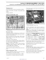
1
R1503motr165A
4-TEC ENGINES
1. Throttle position sensor (TPS)
1
R1503motr271A
ALL 4-TEC SUPERCHARGED ENGINES
1. Throttle position sensor (TPS)
IMPORTANT:
Prior to testing the TPS, ensure
that mechanical components/adjustments are
adequate according to THROTTLE BODY above.
The EMS may generate several fault codes per-
taining to the TPS. Refer to SYSTEM FAULT
CODES in DIAGNOSTIC PROCEDURES section
for more information.
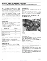
Wear Test
While engine is not running, activate throttle and
pay attention for smooth operation without physi-
cal stops of the cable.
Using the vehicle communication kit (VCK) with
the B.U.D.S. software, use the
Throttle Opening
display under
Monitoring
tab.
Slowly and regularly depress the throttle. Ob-
serve the needle movement.
It must change
gradually and regularly as you move the throttle.
If the needle “sticks”, bounces, suddenly drops
or if any discrepancy between the throttle move-
ment and the needle movement is noticed, it
indicates a worn TPS that needs to be replaced.
Voltage Test
Check the ECM voltage output from to the throttle
position sensor.
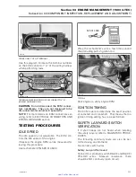
Disconnect connector from throttle position sen-
sor. To unlock connector, insert a small screwdriv-
er between the folded tab.
NOTE:
On the
Supercharged Models
, a mirror
is useful to see under throttle body.
120
smr2005-013
www.SeaDooManuals.net


