


Section 04 ENGINE MANAGEMENT (1503 4-TEC)
Subsection 03 (COMPONENT INSPECTION, REPLACEMENT AND ADJUSTMENT)
13
4
R1503motr270A
3
2
5 6
7 8
9 10
11
12
14
18
19
20
1
16 15
17
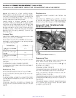
ALL 4-TEC SUPERCHARGED ENGINES
1. ECM connector
2. CTS connector
3. EGTS connector
4. CAPS connector
5. Fuel injector connector (cylinder 1)
6. Ignition coil connector (cylinder 1)
7. Fuel injector connector (cylinder 2)
8. Ignition coil connector (cylinder 2)
9. Fuel injector connector (cylinder 3)
10. Ignition coil connector (cylinder 3)
11. TOPS valve connector
12. connector
13. TPS connector
14. Idle bypass valve connector
15. MATS connector
16. Engine connector
17. MAPS connector
18. OPS connector
19. KS connector
20. CPS connector
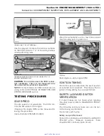
Resistance Test
Check continuity of the circuits according to the
wiring diagram in the ELECTRICAL CONNEC-
TORS AND WIRING DIAGRAMS section of this
manual.
If wiring harness is good, check the respective
sensor/actuator as described in this section.
Otherwise, repair the connectors, replace the
wiring harness or the ECM/MPEM as diagnosed.
Removal
Remove fuel rail cover.
Disconnect the wiring harness from all sensors/
actuators.
Disconnect the ECM connector from the ECM.
Cut all tie raps which are holding the wiring har-
ness in position.
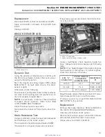
1
R1503motr200A
TYPICAL
1. Wiring harness
Remove complete wiring harness.
Installation
First connect the ECM connector A and fix the
harness on the wiring support with a locking tie.
1
R1503motr201A
1. Locking tie
Lead the cable bundle with the injector and igni-
tion coil connectors to the fuel rail and fix it also
by using 4 locking ties.
114
smr2005-013
www.SeaDooManuals.net


