


Section 04 ENGINE MANAGEMENT (1503 4-TEC)
Subsection 03 (COMPONENT INSPECTION, REPLACEMENT AND ADJUSTMENT)
– Check if crankcase blow-by pressure stays be-
low 40 kPa (6 PSI) as described in the DYNAMIC
TEST below. If not, inspect TOPS valve.
– Check OSPS wiring and connectors.
Re-
place/repair if required.
– Check OSPS.
Dynamic Test
WARNING
The TOPS system might be pressurized. Stop
the engine and wait at least 30 seconds before
opening the oil filler cap, to release the pres-
sure.
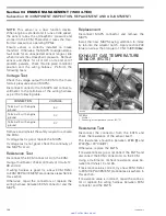
To check the function of the OSPS (oil separator
pressure sensor), proceed as follows.
Remove oil dipstick from engine.
Using appropriate tubes, install the engine leak
test pump (P/N 529 021 800) on dipstick tube. En-
sure to have a tight fit.
Start engine. Spray soapy water on the tubes
from the pump to the dipstick tube to ensure
there is no leak. If so, correct the leak before
measuring the pressure.
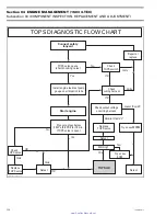
If the engine blow-by pressure does not reach
40 kPa (6 PSI), the CHECK ENGINE message is
present in the cluster and the fault code P1202 is
active, check the following points:
– Check OSPS wiring and connectors. Replace/
repair if required.
– Replace OSPS if wiring and connectors are in
good condition.
If the engine blow-by pressure does reach 40 kPa
(6 PSI) and does not drop, verify the TOPS valve
operation.
WARNING
Stop the engine and wait at least 30 seconds
before removing the pump and tubes, so that
pressure drops.
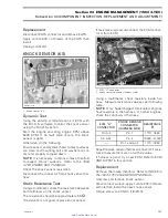
Resistance Test
Disconnect the connector from the OSPS and use
a multimeter to check the resistance between
OSPS terminal and engine ground while engine
is stopped (without blow-by pressure) and while
engine is running (with blow-by pressure).
When engine is stopped and the blow-by pressure
is released, the resistance of the OSPS is close to
0
(normally closed switch).
When engine is running and the crankcase blow-
by pressure exceeds 40 kPa (6 PSI), the resistance
is infinitely high.
NOTE:
In order to achieve the threshold value,
the TOPS valve must be disconnected and the
fault code P1200 will be activated. To measure
the crankcase blow-by pressure, install the pump
gauge tester as per procedure in the DYNAMIC
TEST.
If resistance values are incorrect, replace OSPS.
If the values are correct, check the continuity of
the wiring harness.
Disconnect the ECM connector A from the ECM
and check continuity of circuit 31.
Repair/replace wiring harness as required.
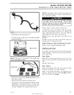
TOPS SWITCH
Disconnect TOPS switch and remove from MPEM
bracket.
smr2005-013-001_a
1. Tops switch
Install a temporary connector with 3 wires to
TOPS switch.
Connect battery positive terminal to pin A of con-
nector and battery ground to pin B.
130
smr2005-013
www.SeaDooManuals.net


