


Section 08 STEERING SYSTEM
Subsection 01 (STEERING SYSTEM)
F07K0UA
1
1
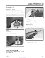
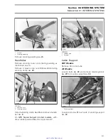
1. Pad must not exceed stopper
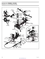
All Models
Position handlebar
no. 9
. Install steering clamp
no. 25
and secure with new elastic stop nuts M8.
Torque nuts to 26 N•m (19 lbf•ft) as per the fol-
lowing sequence.
F07K0VA
1
3
2
4
TORQUE SEQUENCE
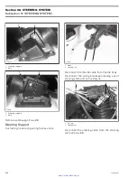
Ball Joint
Secure the steering cable ball joint
no. 44
to the
nozzle as per following illustration.
CAUTION:
Ensure the ball joint is parallel
(± 10°) to the nozzle arm.
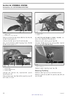
1
F19J0CA
2
TYPICAL
1. Ball joint below steering arm
2. Torque nut to 7 N•m (62 lbf•
in
)
ALIGNMENT
Position handlebar in straight ahead position by
measuring each side the distance from handlebar
grip end to floorboard.
F01K07A
1
TYPICAL
1. Measuring handlebar grip end/floorboard distance
Check jet pump nozzle position by placing a
straight edge on nozzle outer end. Measure the
distance on each side of the straight edge. It
must be equalled.
236
smr2005-022
www.SeaDooManuals.net


