


Section 07 PROPULSION
Subsection 02 (DRIVE SYSTEM)
F01I0FA
3
2
1
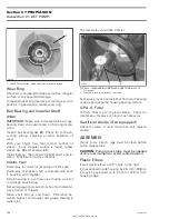
TYPICAL
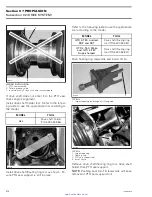
1. Surface condition
2. Groove condition
3. Splines condition
Excessive deflection could cause vibration and
damage to drive shaft splines, impeller, flywheel
or floating ring.
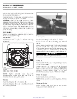
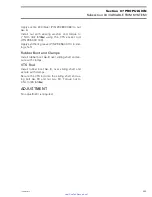
Place drive shaft on V-blocks and set-up a dial
gauge in center of shaft. Slowly rotate shaft; dif-
ference between highest and lowest dial gauge
reading is deflection. Refer to the following illus-
tration.
Maximum permissible deflection is 0.5 mm
(.020 in).
1
2
F01J15A
MEASURING DRIVE SHAFT DEFLECTION
1. Dial gauge
2. V-blocks
Damper
4-TEC Models
Discard damper
no. 8
to install a new one.
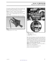
Floating Ring and O-Ring
Inspect condition of O-rings
no. 9
and floating ring
contact surface.
F01I0GA
1
2
1. O-rings
2. Floating ring contact surface
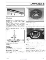
PTO Seal
Discard both O-rings
no. 10
inside PTO seal and
install new ones.
F18C01A
1
1. O-rings
Inspect PTO seal assembly.
Refer to PTO
HOUSING/MAGNETO section.
Boot
Inspect the condition of boot. If there is any dam-
age or evidence of wear, replace it.
INSTALLATION
Installation is essentially the reverse of removal
procedure. However, pay particular attention to
the following.
smr2005-020
209
www.SeaDooManuals.net


