


Section 06 ELECTRICAL SYSTEM
Subsection 03 (STARTING SYSTEM)
GENERAL
Causes of troubles are not necessarily related to
starter but may be due to a burnt fuse, faulty
battery, start/stop switch, safety lanyard switch,
MPEM or ECM, solenoid, electrical cables or con-
nections.
Check these components before removing starter.
Consult also the starting system troubleshooting
table for a general view of possible problems.
WARNING
Short circuiting electric starter is always
a danger, therefore disconnect the battery
ground cable before carrying out any kind
of maintenance on starting system. Do not
place tools on battery.
Electrical Cables or Connections
Check all connections, cables and wires. Tighten
any loose cables. Replace any chafed wires.
Fuse
Make sure the 10 A fuse (#9 on wiring diagram)
fuse on the MPEM and the 30 A main fuse (start-
ing system) besides the MPEM are in good condi-
tion.
The solenoid may be the cause of a burnt fuse. If
the solenoid checks good, one of the accessory
may be defective.
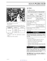
Battery
To check battery condition, refer to CHARGING
SYSTEM.
Engine Control Module (ECM)
If 2 short beeps are not heard when installing the
safety lanyard, refer to ENGINE MANAGEMENT.
Engine Start/Stop Switch
A quick operation test can be done using the ve-
hicle communication kit (VCK) with the B.U.D.S.
software, using the
Monitoring
tab. Press the
start button and look at the
Start button
LED. It
should turn on, indicating the starting system is
working on the input side of the starting system
(start button, MPEM, ECM and wiring). You know
now the problem is on the output side of the start-
ing system (MPEM output signal to starting so-
lenoid, wiring harness going to the solenoid and
starter motor). Otherwise, check the input side
as follows.
Disconnect the start/stop switch connector. Us-
ing an ohmmeter, connect test probes to YEL-
LOW/RED and PURPLE wires.
Measure resistance, it must be an open circuit
(switch is normally open).
Depress and hold
switch, the ohmmeter should read lower than
200 ohms. Otherwise, replace switch. Recon-
nect connector.
Test continuity of circuit 2-23. If it is faulty, re-
pair harness/connectors. Otherwise, try a new
MPEM.
Test continuity of circuit B-19. If it is faulty, repair
harness/connectors. Otherwise, try a new ECM.
Solenoid
NOTE:
Solenoid is located besides the MPEM.
Inspect connections and clean as necessary.
CONTINUITY TEST
With a multimeter, check primary winding resis-
tance.
It should be approximately 5 ohms.
There should be no continuity between the posi-
tive posts of the solenoid.
VOLTAGE TEST
Depress start/stop button and measure the volt-
age on the solenoid positive posts with a multi-
meter.
If there is no voltage and battery is in good condi-
tion, replace the solenoid.
smr2005-017
167
www.SeaDooManuals.net


