


Date Code 20011112
Line Current Differential, Distance, Out-of-Step, Overcurrent,
3-15
Voltage, Synchronism Check, and Frequency Elements
SEL-311L Instruction Manual
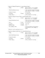
CTR (1–6000)
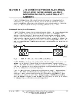
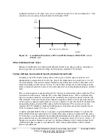
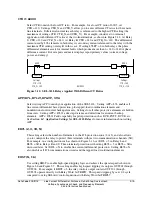
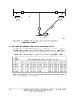
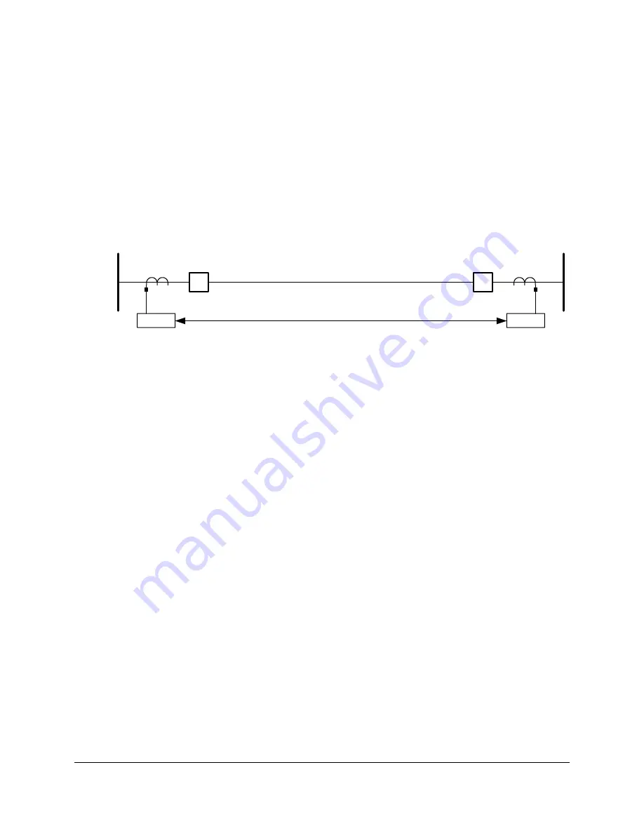
Select CTR to match the local CT ratio. For example, for a local CT ratio of 600:5, set
CTR = 120. Settings CTR_X and CTR_Y allow you to enter different CT ratios for the remote
line terminals. Differential current in each relay is referenced to the highest CTR setting (the
maximum of settings CTR, CTR_X, and CTR_Y). For example, consider a two terminal
application with different CT ratios at the two line terminals, as shown in Figure 3.12. At Relay
S, CTR = 120 and CTR_X = 240. At Relay R, CTR = 240, and CTR_X = 120. The differential
current used by 87L elements in both relays is secondary current referenced to the relay with the
maximum CTR setting, or relay R in this case. If setting 87LPP = 6 in both relays, the phase
differential elements assert for internal faults which produce more than 6 • 240 = 1440 A phase
difference current. Event reports and meter displays report primary values (current, voltage,
power, and energy).
SEL-311L
SEL-311L
Settings:
CTR = 120
CTR_X = 240
Settings:
CTR = 240
CTR_X = 120
1200:5
600:5
M311L093
R
S
Figure 3.12: SEL-311L Relays Applied With Different CT Ratios
APP (87L, 87L21, 87L21P, 311L)
Select setting APP to match your application of the SEL-311L. Setting APP = 87L enables all
line current differential based protection, plus tapped-load coordination elements and
nondirectional overcurrent backup elements. Settings for all other protective elements are hidden
from view. Setting APP = 87L21 adds step-distance and directional overcurrent backup
elements. APP = 87L21P adds capability for pilot protection such as DCB, POTT, DCUB, etc.
See
Section 14: Application Settings for SEL-311L Relays
for more information about setting
APP.
E87L (2, 3, 3R, N)
This setting selects the number of terminals in the 87L protection zone (2 or 3), and also allows
you to configure the relay to protect three terminals with just two communications channels (3R).
For example, in a configuration such as shown in Figure 3.16, set E87L = 3 in Relay L and
E87L = 3R in Relays R and S. Three-terminal protection with setting E87L = 3 or E87L = 3R is
discussed later. Set E87L = N to disable line current differential protection. Setting E87L = N
also disables all 87L communications circuits and the tapped-load coordination elements.
EHST (N, 1–6)
Use setting EHST to enable high-speed tripping logic and achieve the operate speeds shown in
Figure 3.6 and Figure 3.7. This setting enables high speed tripping via outputs OUT201 through
OUT206. For example, if EHST = 3, the relay controls output contacts OUT201 through
OUT203 operate directly with Relay Word bit TRIP87. This speeds tripping by over 1/2 cycle
compared to using SEL
OGIC
control equations with Relay Word bit TRIP87.
Содержание SEL-311L
Страница 6: ......
Страница 8: ......
Страница 26: ......
Страница 54: ......
Страница 144: ......
Страница 203: ...Date Code 20010625 Trip and Target Logic 5 27 SEL 311L Instruction Manual Figure 5 12 DCUB Logic ...
Страница 216: ......
Страница 252: ......
Страница 302: ......
Страница 338: ......
Страница 480: ......
Страница 484: ......
Страница 486: ......
Страница 502: ......
Страница 532: ...12 28 Standard Event Reports and SER Date Code 20010625 SEL 311L Instruction Manual 4 ...
Страница 552: ......
Страница 554: ......
Страница 574: ......
Страница 576: ......
Страница 596: ......
Страница 602: ......
Страница 628: ......
Страница 656: ......
Страница 662: ......
Страница 664: ......
Страница 688: ......
Страница 700: ......
Страница 716: ......
Страница 722: ......
Страница 734: ......


