


Date Code 20011112
Line Current Differential, Distance, Out-of-Step, Overcurrent,
3-79
Voltage, Synchronism Check, and Frequency Elements
SEL-311L Instruction Manual
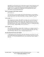
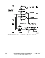
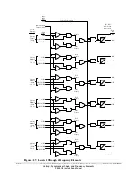
Block Synchronism Check Conditions
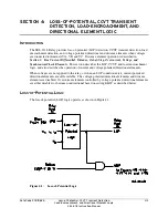
Refer to Figure 3.53.
The synchronism check element slip frequency calculator runs if voltages V
A
, V
P
, and V
S
are
healthy (59VA, 59VP, and 59VS asserted to logical 1) and the SEL
OGIC
control equation setting
BSYNCH (Block Synchronism Check) is deasserted (= logical 0). Setting BSYNCH is most
commonly set to block synchronism check operation when the circuit breaker is closed
(synchronism check is only needed when the circuit breaker is open):
BSYNCH = IN101
(input IN101 connected to a breaker auxiliary 52a contact)
BSYNCH = !IN101
(input IN101 connected to a breaker auxiliary 52b contact)
In addition, synchronism check operation can be blocked when the relay is tripping:
BSYNCH = ... + TRIP
Slip Frequency Calculator
Refer to Figure 3.53.
The synchronism check element Slip Frequency Calculator in Figure 3.53 runs if voltages V
P
, V
S
,
and V
A
are healthy (59VP, 59VS, and 59VA asserted to logical 1) and the SEL
OGIC
control
equation setting BSYNCH (Block Synchronism Check) is deasserted (= logical 0). The Slip
Frequency Calculator output is:
Slip Frequency = f
P
–f
S
(in units of Hz = slip cycles/second)
f
P
= frequency of voltage V
P
(in units of Hz = cycles/second)
[determined from V
A
]
f
S
= frequency of voltage V
S
(in units of Hz = cycles/second)
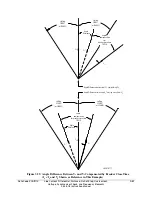
A complete slip cycle is one single 360-degree revolution of one voltage (e.g., V
S
) by another
voltage (e.g., V
P
). Both voltages are thought of as revolving phasor-wise, so the “slipping” of V
S
past V
P
is the relative revolving of V
S
past V
P
.
For example, in Figure 3.53, if voltage V
P
has a frequency of 59.95 Hz and voltage V
S
has a
frequency of 60.05 Hz, the difference between them is the slip frequency:
Slip Frequency = 59.95 Hz - 60.05 Hz = -0.10 Hz = -0.10 slip cycles/second
The slip frequency in this example is negative, indicating that voltage V
S
is not “slipping” behind
voltage V
P
, but in fact “slipping” ahead of voltage V
P
. In a time period of one second, the angular
distance between voltage V
P
and voltage V
S
changes by 0.10 slip cycles, which translates into:
0.10 slip cycles/second • (360°/slip cycle) • 1 second = 36°
Thus, in a time period of one second, the angular distance between voltage V
P
and voltage V
S
changes by 36 degrees.
The absolute value of the Slip Frequency output is run through a comparator and if the slip
frequency is less than the maximum slip frequency setting, 25SF, Relay Word bit SF asserts to
logical 1.
Содержание SEL-311L
Страница 6: ......
Страница 8: ......
Страница 26: ......
Страница 54: ......
Страница 144: ......
Страница 203: ...Date Code 20010625 Trip and Target Logic 5 27 SEL 311L Instruction Manual Figure 5 12 DCUB Logic ...
Страница 216: ......
Страница 252: ......
Страница 302: ......
Страница 338: ......
Страница 480: ......
Страница 484: ......
Страница 486: ......
Страница 502: ......
Страница 532: ...12 28 Standard Event Reports and SER Date Code 20010625 SEL 311L Instruction Manual 4 ...
Страница 552: ......
Страница 554: ......
Страница 574: ......
Страница 576: ......
Страница 596: ......
Страница 602: ......
Страница 628: ......
Страница 656: ......
Страница 662: ......
Страница 664: ......
Страница 688: ......
Страница 700: ......
Страница 716: ......
Страница 722: ......
Страница 734: ......


