


Date Code 20011112
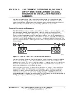
Line Current Differential, Distance, Out-of-Step, Overcurrent,
3-9
Voltage, Synchronism Check, and Frequency Elements
SEL-311L Instruction Manual
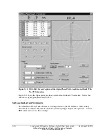
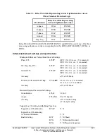
Negative-Sequence 87L Settings and Alpha Plane Settings
Three settings control operation of the negative-sequence 87L element. Refer to Figure 3.3.
87LANG
The angular extent of the restraint region.
87LR
The outer radius of the restraint region (the inner radius is the reciprocal of
87LR).
87L2P
The 3I2 difference current which qualifies tripping when the Alpha plane ratio
lies outside the restraint region.
Settings 87LANG and 87LR are common for all line current differential elements. There are not
separate restraint region settings for each type of element.
Set 87LANG as describe previously in the phase 87L discussion.
Set 87LR as described previously in the phase 87L discussion.
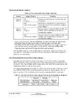
Set 87L2P to reliably detect all internal unbalanced faults, but above expected maximum line
charging current unbalance during steady state conditions. Line charging current unbalance is
usually small. Consider setting 87L2P at 10% of nominal current, or 0.5 A for a 5 A relay. This
is the factory default setting for 87L2P.
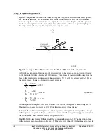
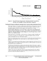
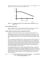
The settings defined above are factory default. They are also the settings used to produce the
operate speed curves shown in Figure 3.7 (using high-speed output contacts).
M311L091
87L2, 87LG Trip Speed
0.6
0.8
1.0
1.2
1.4
1.6
1.8
2.0
2.2
1.2
2.0
3.0
4.0
5.0
6.0
7.0
8.0
9.0
10.0
3I2 or 3I0 Difference Current (per unit of 87L2P, 87LGP)
Trip
Ti
m
e
(Cyc
les)
Maximum
Minimum
Figure 3.7: 87LG and 87L2 Element Trip Speeds for Symmetrical Fault Currents With
87LANG = 195 and 87LR = 6 Using a Direct Fiber Connection.
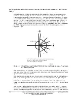
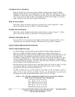
These settings give excellent speed and sensitivity for internal unbalanced faults as shown in
Figure 3.8. For load currents less than 1/3 Inom, the ground fault sensitivity is determined by the
minimum 87L2P and 87LGP pickup settings of 0.5 A, and is 132.8 ohms secondary referenced to
Vnom = 66.4 V. Above 1/3 Inom, ground fault sensitivity is determined by the ratio |I2| / |I1| for
87L2, and |I0| / |I1| for 87LG. The 87L2 element enables when |I2| / |I1| > 0.05 from at least one
terminal. Likewise, 87LG is enabled when |I0| / |I1| > 0.05 from at least one terminal. This
linearly decreases the fault resistance coverage from 132.8 ohms secondary worst case at 1/3 of
Содержание SEL-311L
Страница 6: ......
Страница 8: ......
Страница 26: ......
Страница 54: ......
Страница 144: ......
Страница 203: ...Date Code 20010625 Trip and Target Logic 5 27 SEL 311L Instruction Manual Figure 5 12 DCUB Logic ...
Страница 216: ......
Страница 252: ......
Страница 302: ......
Страница 338: ......
Страница 480: ......
Страница 484: ......
Страница 486: ......
Страница 502: ......
Страница 532: ...12 28 Standard Event Reports and SER Date Code 20010625 SEL 311L Instruction Manual 4 ...
Страница 552: ......
Страница 554: ......
Страница 574: ......
Страница 576: ......
Страница 596: ......
Страница 602: ......
Страница 628: ......
Страница 656: ......
Страница 662: ......
Страница 664: ......
Страница 688: ......
Страница 700: ......
Страница 716: ......
Страница 722: ......
Страница 734: ......