background image


30.30.01.01648/06 

www.schmalz.com 

EN   | 43 

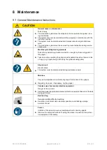
8  Maintenance 

  General Maintenance Instructions 


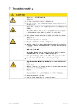
CAUTION 


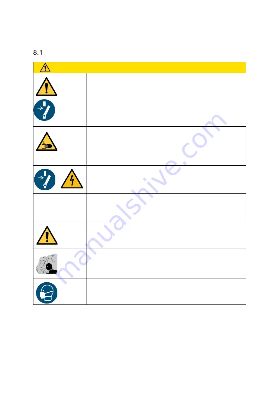
General notes on maintenance 


Risk of injury 

► 


The production system must be stopped in the area where the system is be-
ing maintained. 

► 


The system may only be maintained at the workplace in accordance with the 
instruction manual. 

►  The system must be disconnected and depressurized during maintenance 

work. 


► 


The production system must be secured to prevent activation during mainte-
nance work. 


Machinery mobility/moving elements 


Risk of body parts being crushed, pulled in or caught by the moving parts of 
the gripper 

► 


Take care when operating the gripper and its assemblies when there is a risk 
of injury (e.g. fingers being crushed by the cylinder/sealing plate) 


Short-circuit 


Electric shock 

► 


The system must be disconnected during maintenance work. 


Moisture 


Very wet workpieces can permanently impair the function of the gripper 

►  Regularly clean and, if necessary, dry the gripper 


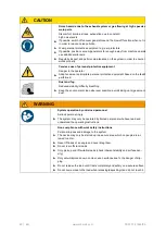
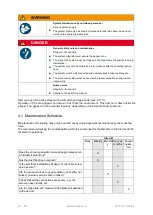
Careless use of personal protective equipment


Danger to the operator 


► 


Adapt and wear appropriate personal protective equipment based on the task 
being performed. 


Dust and fog 


Reduced visibility/difficulty breathing 

►  Keep the environment clean wherever possible; avoid kicking up large 

amounts of dust. 


Fumes 


Irritation of the skin and mucous membranes due to cleaning agents 


►  Observe the safety instructions for using the cleaner in question. Use protec-

tive equipment if necessary. 


Содержание FMHD

Страница 1: ...www schmalz com Innovative Vacuum for Automation EN Instruction Manual Vacuum area gripper FMHD 30 30 01 01648 06 02 2022 ...

Страница 2: ...alz GmbH retains the rights established thereby Re production of the contents in full or in part is only permitted within the limits of the legal provisions of copyright law Any modifications to or abridgments of the document are prohibited without explicit writ ten agreement from J Schmalz GmbH Contact J Schmalz GmbH Johannes Schmalz Str 1 72293 Glatten Germany Tel 49 0 7443 2403 0 Fax 49 0 7443 ...

Страница 3: ...rom the Transportation Packaging 23 Storage 23 5 Start of Operations and Setup 24 Start of Operations 24 Vacuum area grippers 27 Connections for Functional Cover 27 Vacuum Connection 28 Connection of Adapter Set SBX 28 Electrical Connections 29 5 6 1 Solenoid Valves 29 5 6 2 Electrical Connection 29 5 6 3 LED Display in the Standard Version 31 5 6 4 LED Display with Impulse Valve 31 6 Operation 32...

Страница 4: ...and Cleaning the Gripper 47 Overview of the Tightening Torque of the Screws 50 Checking the System for Leaks 51 9 Spare and Wearing Parts 52 10 Accessories 55 11 Pneumatic Circuit Diagram 56 Pneumatic Circuit Diagram of the Standard Version FMHD 56 Pneumatic Circuit Diagram of the FMHD with Ventilation Cylinder 57 Pneumatic Circuit Diagram of the FMHD with Impulse Valve 58 Pneumatic Circuit Diagra...

Страница 5: ...it is not avoided WARNING Type and source of danger Consequence Remedial action Caution This warning informs the user of a risk that could result in injury if it is not avoided CAUTION Type and source of danger Consequence Remedial action Attention This warning informs the user of a risk that could result in damage to property if it is not avoided ATTENTION Type and source of danger Consequence Re...

Страница 6: ...n Description Icon Description Pollution warning Crushing injury Suspended load Hand injury warning Electrical voltage General warning symbol Hearing damage Warning of overpressure Electric shock Mandatory Symbols Explanation of the mandatory symbols used in the operating instructions Icon Description Icon Description Observe the instructions Wear eye protection Use protective footwear Activate pr...

Страница 7: ...d state Only qualified specialist personnel mechanics and electricians may perform the installation Qualified specialist personnel are persons who have received technical training and have the knowledge and experience including knowledge of applicable regulations necessary to enable them to recognize possible dangers and implement the appropriate safety measures while per forming tasks General saf...

Страница 8: ...e or animals are allowed to enter WARNING Suspended loads Personal injuries and damage to the system Never stand under suspended loads The system is mounted on the load suspension provided by the customer using the T slots designated for this purpose The customer also provides a control device The system can only be used lying horizontally You must consult the manufacturer regarding tilted positio...

Страница 9: ...example 1 Gripper type FMHD FMHD 2 Check valve CV1 CV2 automatic assignment Standard version 3 Length L From 350 mm to 3500mm 14 mm grid 840 mm 4 Grid 2R28 3R22 special grid 2R28 5 Foam type Foam type specification depending on the application O20 6 Cylinder position L3 Measured from the left side of the enclosure to the center of the mounting plate Left 155 mm 7 Plate PNP for impulse valve PNP 8 ...

Страница 10: ... or the suction elements dirt wear etc The automated handling system to which the system was attached by the customer is responsible for motion in the various axes Description of Functions Valve Technology SVK There are valves with sliders balls in the valve plate see Section 2 2 G If they are not covered by a workpiece in the moment that suction begins the sliders balls will close the valve For t...

Страница 11: ...or external vacuum generation D Base section E T slot with quick release clamps F End cover without function modules G Valve section with adhesive valve film H Masking film I Quick change section J Sealing plate K Sealing plate L Slider spherical D C B A E F G I J Vacuum reservoir Valve cham ber L Fig Vacuum area gripper FMHD cross section K D G I H ...

Страница 12: ...ditional connections A vacuum gauge or vacuum switch can be attached to connection A A multi pin connector for valve control is also attached here Only the two 1 8 threads are integrated into the opposite end cover without function modules F a measuring device to display the vacuum in the vacuum reservoir can be attached to both threads N M O Fig Vacuum area gripper FMHD with ejector SBPL and adap...

Страница 13: ...version do not remove the plug 1 8 Blow off connection not used in the version with the ventilation cylinder plug 1 9 For covers prior to May 2022 this is connected to connection B and has no function for co vers after May 2022 connection B is connected to bore 1 9 an additional sensor or vacuum pressure gauge can be connected 1 1 Connection A Connection B Connections A and B can be used to connec...

Страница 14: ...ing cylinder If compressed air is applied the cylinder ex tends and closes the Suction OFF reservoir chamber 1 6 Bore Hole for Vacuum Measurement Connections A and B are connected to the bore holes 1 6 on both sides Connection B since May 2022 see the information under 1 1 1 7 Ventilation Cylinder Connection In the standard version this connection is closed with a plug that must not be removed Whe...

Страница 15: ...with the sealing on the end covers this is how the valve chamber is sealed E Sliding Blocks The t slots are used for flexible mechanical attachment of the gripper using the sliding blocks Suitable attachment kits are listed in the Accessories section The quick release clamps are fastened to the side t slots using sliding blocks Additional sensors can also be attached to the side t slots B Separati...

Страница 16: ...n their valves These can be replaced as necessary L Sliders Spherical sliders are located in the valves These sliders close the valves under which there is no work piece A spherical slider must be located in every valve I Quick Change Section The quick change section I is suspended on one side in a designated slot on the base section and fixed on the other side with quick release clamps The sealin...

Страница 17: ...tolerances we recommend adjusting the height of the gripper every time you replace the foam For safe use we recommend at least 50 foam compression when picking up the workpieces in order to achieve optimal function and foam service life This flexing makes the foam more permeable to air When a high number of working cycles is reached it may be necessary to replace the foam even if there is no visib...

Страница 18: ...ting the cylinder not shown 2 5 Sealing plate 2 6 Sealing plate sealing 2 7 Mounting plate sealing 2 8 Plug in screw union compressed air connection 2 9 Quick exhaust valve ensure that they are properly connected 2 10 Y piece exhaust 2 11 Exhaust connection 2 12 Compressed air connection 2 6 Note the direction of the quick change valve 2 9 2 1 2 8 2 3 2 7 2 10 2 5 2 12 2 2 2 11 ...

Страница 19: ... together with a dust filter Further information about the dust filter and ejector can be found in the relevant documentation O End cover with ejector SBPL and filter 2 1 Ejector silencer must not be closed 2 2 Vacuum ejector SBPL 2 3 Compressed air connection for vacuum ejector 2 4 Dust filter 2 5 End cover with G1 1 4 connection thread 2 6 Form seal for housing cover 2 5 2 6 2 1 2 4 2 3 2 2 ...

Страница 20: ...mm Length 1050 mm Grid 2R28 70 90 315 1 497 16 FMHD Width 170 mm Length 1260 mm Grid 2R28 85 90 378 1 818 19 5 FMHD Width 170 mm Length 1050 mm Grid 3R22 132 90 315 1 054 16 FMHD Width 250 mm Length 1050 mm Grid 2R28 70 90 315 2 637 19 FMHD Ejector SBPL 150 HV Width 170 mm Length 1 050 mm Grid 2R28 70 90 4754 1 497 1 At higher vacuum levels a vacuum limiter valve must be used 2 At a vacuum of 0 3 ...

Страница 21: ...126 V1 CA1 Extra wide gripper FMHD 250 CV 1 1050 2R28 O20 C138L P S60 126 V1 Gripper with 3R22 grid FMHD CV2 1050 3R22 O20 C152L P S60 126 V1 CA1 Dimensions H H11 H22 L L1 L2 L3 D 111 6 158 6 20 1 050 1 057 83 126 152 60 116 6 163 6 20 1 050 1 057 83 126 138 60 111 6 158 6 20 1 050 1 057 83 126 152 60 L44 B5 B16 B27 B38 Y ZA 1 004 170 191 3 175 5 168 120 28 1 004 250 250 175 5 250 120 28 1 004 170...

Страница 22: ... instructions may unload and transport the product Delivery 4 1 1Items Included in Delivery For the exact items included in delivery please refer to the order confirmation The delivery documents list the shipping weight and dimensions Note the system weight and dimen sions when choosing suitable lifting equipment Note The instruction manual is part of the system and must be kept with the system ev...

Страница 23: ...ove the product Attach a suitable lifting device to the system Now lift the system so that it is freely suspended after all other packaging elements are removed Storage The system must be stored in its original packaging as long as it is not being used and is to be stored for any period of time ATTENTION Incorrect storage of the system Material damage to the system The system may only be stored as...

Страница 24: ...the bottom of the gripper and a surface High pressure Placement release of compressed air lines The system integrator must secure the danger zone Regularly inspect the gripper and perform regular maintenance in order to de tect and replace porous compressed air lines in good time Replace defective connectors Stored energy vacuum Body parts could be crushed cut sucked in caught or sliced if the fla...

Страница 25: ...the task being performed Dust and fog Reduced visibility difficulty breathing Keep the environment clean wherever possible avoid kicking up large amounts of dust WARNING System setup by untrained personnel Serious personal injury The system must only be set up by trained personnel who have read and un derstood the operating instructions Non compliance with work safety instructions Personal injurie...

Страница 26: ...ing set up The system may only be set up at the workplace in accordance with the oper ating instructions The system must be disconnected during setup The production system must be secured to prevent activation during setup Acceleration deceleration kinetic energy Danger to life and limb See general safety notes on the start of operations Danger of falling objects gravity Danger to life and limb Se...

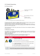
Страница 27: ...the system Do not connect the gripper to the handling device with an insulating intermedi ate piece Connections for Functional Cover 1 Electrical connection 2 Compressed air connection 3 Measurement point for vacuum 4 Ventilation for control valves The compressed air is connected using the quick connect coupling which is located on the sealing plate and is included in delivery Requirements for the...

Страница 28: ... Once vacuum is applied in a gripper it immediately begins suction when the cylin der is open Connection of Adapter Set SBX Customers that are using the vacuum area gripper SBX can replace it with the gripper FMHD which was designed especially for this purpose if the vacuum area gripper becomes damaged It can be replaced 1 1 in the existing system with an adapter cable and additional mechanical co...

Страница 29: ... integrated into the end cover 24V DC 10 max power consumption 2 W 2 3 W when using the impulse valve rated current 0 1 A Standard PNP switching The plug connectors must not be connected or disconnected when the system is live The power supply and signal inputs have a maximum line length of 30 meters DANGER Inappropriate voltage supply Electric shock destruction of the electrical components Connec...

Страница 30: ...adapter set SBX with ventilation cylinder Pin Function PNP 1 Suction signal input controlling the separating cylinder 2 Blow off signal input depositing workpieces 3 Ground 4 Not used 5 Ground 6 Not used Plug for the adapter set SBX with ejector SBPL Pin Function PNP 1 Suction signal input controlling the separating cylinder 2 Vent signal input depositing workpieces 3 Ejector signal input switchin...

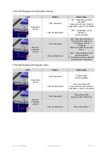
Страница 31: ...ed on depositing the workpiece or ventilation cylinder extended applying suction to the work piece LED not illuminated OFF blow off switched off suction applied or ventilation cylinder retracted depositing the workpiece 5 6 4LED Display with Impulse Valve LED Status Valve status Separating cylinder LED illuminated Cylinder OFF suction applied LED not illuminated Extend cylinder ON reservoir and va...

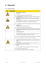
Страница 32: ... danger zone Regularly inspect the gripper and perform regular maintenance in order to de tect and replace porous compressed air lines in good time Replace defective connectors Stored energy vacuum Body parts could be crushed cut sucked in caught or sliced if the vacuum area gripper is abruptly attached to a workpiece or a surface Do not place any body parts between the bottom of the gripper and a...

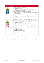
Страница 33: ...e task being performed Dust and fog Reduced visibility difficulty breathing Keep the environment clean wherever possible avoid kicking up large amounts of dust WARNING System operation by untrained personnel Serious personal injury The system may only be operated by trained personnel who have read and understood the operating instructions Non compliance with work safety instructions Personal injur...

Страница 34: ...e case of unforeseeable events e g emergency stop Danger of falling objects gravity due to falling objects Danger to life and limb See general safety notes on the start of operations Never stand under suspended loads Do not place any body parts under the suspended load or the system The system s maximum permitted lift capacity must not be exceeded Human error Danger to life and limb Adhere to the ...

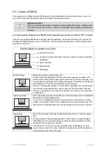
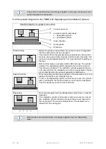
Страница 35: ...of time this process takes varies based on the suction bar type vac uum generator capacity and the length Generally this process is started ap proximately 0 5 to 5 seconds before picking up the load When the Separating cylinder control valve is activated the cylinder piston rod extends and separates the vacuum reservoir from the valve chamber Vacuum is generated in the reservoir chamber when the v...

Страница 36: ...ht up The cylinder extends The separating cylinder separates the vacuum reservoir from the valve chamber The ventilation cylinder separates the vac uum reservoir from the atmosphere Vacuum is generated in the res ervoir chamber when the vacuum generator is switched on Applying suction Once the sealing mat has been placed on the workpiece and is com pressed the system can start picking it up To do ...

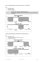
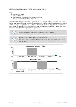
Страница 37: ...ing cylinder EMC Voltage 0 V Pretensioning Applying suction Depositing Time 24 V Blow off EMC Voltage 0 V Pretensioning Applying suction Depositing Idle state Time 6 2 4Functional Diagram of FMHD with Ventilation Cylinder Using Separating cylinder Ventilation cylinder instead of Blow off function Two NC control valves 24 V Separating cylinder EMC Voltage 0 V Pretensioning Applying suction Depositi...

Страница 38: ...ulse length of 25 ms is sufficient The impulse length for depositing the workpiece de pends on the vacuum level in the gripper and the type of products being handled The best way to de termine it is through tests during the start of operations For the impulse valve an impulse length of 25 ms is sufficient Duration of the blow off compressed air pulse Depending on the workpiece the blow off process...

Страница 39: ...nger zone Regularly inspect the gripper and perform regular maintenance in order to de tect and replace porous compressed air lines in good time Replace defective connectors Stored energy vacuum Body parts could be crushed cut sucked in caught or sliced if the vacuum area gripper is abruptly attached to a workpiece or a surface Do not place any body parts between the bottom of the gripper and a su...

Страница 40: ...e task being performed Dust and fog Reduced visibility difficulty breathing Keep the environment clean wherever possible avoid kicking up large amounts of dust WARNING System operation by untrained personnel Serious personal injury The system may only be operated by trained personnel who have read and understood the operating instructions Non compliance with work safety instructions Personal injur...

Страница 41: ...e rec ommend that the foam compress by at least 50 Too short retention time for the area gripper on the workpiece Extend the retention time Too fast or jerky lifting of work pieces Optimize the motion Avoid acceleration peaks especially when lifting the work pieces The workpieces to be lifted are not suitable for the area grippers e g non rigid Use a different gripping system External vacuum gen e...

Страница 42: ...lenoid valve is defective Repair or replace the solenoid valve Sealing plate wears out very quickly The vacuum area gripper is angled or makes a grinding noise when applied to the workpiece to be lifted Set it down vertically on the workpiece Material is not optimal Contact our sales department for advice Workpieces are no longer deposited Spring in cylinder is broken the cylinder no longer retrac...

Страница 43: ... operating the gripper and its assemblies when there is a risk of injury e g fingers being crushed by the cylinder sealing plate Short circuit Electric shock The system must be disconnected during maintenance work Moisture Very wet workpieces can permanently impair the function of the gripper Regularly clean and if necessary dry the gripper Careless use of personal protective equipment Danger to t...

Страница 44: ...oft cloth and soap suds max 60 C Operation of the area gripper can draw in dust from the environment This dust can collect inside the gripper The gripper must be cleaned regularly depending on the amount of dust sucked in Maintenance Schedule Maintenance and cleaning may only be carried out by trained specialist personnel or by the manufac turer We recommend checking the contamination within the s...

Страница 45: ...ca tion ambient conditions External Vacuum Generator See the relevant operating instructions Dust Filter When using a dust filter see the relevant operating instructions Cleaning Agents Use cleaning solvents to clean the device not petroleum ether or corrosive liquids Petroleum ether or corrosive liquids destroy the vacuum hoses Quick change Plate To make maintenance easier and replace the foam mo...

Страница 46: ...d ingly when the sealing plates are replaced The foam may not be cleaned with a compressed air gun This would make the foam permeable to air in the places where compressed air was applied If the sealing plate shows mechanical damage it can be repaired up to a certain point using standard vulcanizing adhesive e g adhesive for repairing the inner tubes of bicycles Replacing the sealing plates In ord...

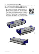
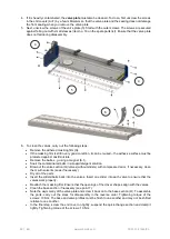
Страница 47: ...nd that no screws are missing etc 2 Check that the attachment parts such as the housing cover cylinder mount ing plate and quick release clamp are secured correctly Check that the quick release clamps are securely attached intact and easy to operate 3 Open the quick release clamp and remove the quick change plate The suspension device must be clean For information on inspecting and re placing the ...

Страница 48: ...lls e g using a magnet 6 1 Soak the contaminated balls in a soap detergent solution Blow out the valve section G valves without sliders with compressed air or if necessary clean them with solvents soak if necessary Dry all of the parts Insert the sliders balls back into the valves Insert one slider into each valve to ensure that the valves work properly Reattach the masking film Ensure that the op...

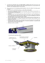
Страница 49: ...e cylinder This is fully retracted when depressurized When you pull on the sealing plate you can notice significant resistance After you release it the cylinder immediately moves back to its starting position If not the cylinder must be replaced Check the sealing Replace defective sealings Remove adhesive residues and any other con tamination when doing so The adhesive surfaces must be kept clean ...

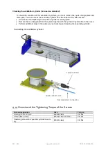
Страница 50: ...unting plate Remove the mounting plate from the system together with the cylinder Pay attention to the hoses Perform additional steps in the same way as checking and cleaning the separating cylinder Overview of the Tightening Torque of the Screws Screw designation Size Torque Housing cover screws M6x30 steel 9 8 Nm Valve plate screws M6x30 stainless steel 9 8 Nm Fastening screws for separator cyli...

Страница 51: ...e displayed on the gauge If the vacuum is not achieved the system must be checked for leakage as follows 1 Check the hose hose connections tubing and the cable screw union on the multi pole plug for damage and leaks and replace them as necessary 2 Check that all the sections and all other functional components are properly assembled 3 Check that the spacer sleeves are still in place between the va...

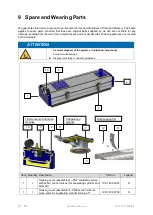
Страница 52: ...rts are not covered by the warranty ATTENTION Incorrect disposal of the system or individual components Environmental damage Disposal according to national guidelines Item Quantity Description Part no Legend 1 1 Housing cover assembled PNP standard version with 2x NC control valves for separating cylinder and blow off 10 01 40 00021 S 1 1 Housing cover assembled PNP version with im pulse valve for...

Страница 53: ...0 01 40 00161 S 1 Ventilation cylinder assembled 10 01 40 00800 S 7 1 Form seal for separating cylinder 91x117x2 mm 10 01 40 00150 W 1 Form seal for ventilation cylinder 120x84x2 mm 10 01 40 00797 W 8 1 Form seal for separating cylinder sealing plate Ø 88 mm 10 01 40 00017 W 1 Form seal for ventilation cylinder sealing plate Ø 82 6 mm 10 01 40 00799 W 9 Mounting kit quick release clamp including a...

Страница 54: ...tion attached comprised of items 18 20 including mounting materials On request S 13 1 Masking film length 3 000 mm cut to size 10 01 40 00108 W 12 Stainless steel bearing 10 01 40 00102 S 20 1 Gripper section FMHD M On request S 21 1 Area gripper suction plate comprised of items 22 24 On request S 22 1 Sealing plate O04 On request S 23 1 Gripper section FMHD U On request S 24 1 Sealing plate On re...

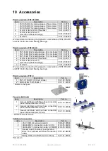
Страница 55: ...k reinforced design 10 01 03 00207 3 FLAN PL 10 01 10 08805 We recommend connecting the gripper to a combination of FST STARR and FST FLEX fixed and floating bearings Rigid suspension FST C Item Description Part no 1 FST C 100 HD1 100 mm stroke 10 01 20 01260 2 MOD FLAN 157x120x64 1 10 01 11 03187 Similar to the figure Vacuum distributor Item Description Part no 1 Vacuum distributor with three hos...

Страница 56: ...ssure in the gripper vacuum reservoir or valve chamber must be limited to a maximum of 0 2 bar Pneumatic Circuit Diagram of the Standard Version FMHD FMHD with separating cylinder and Blow off function Blow off ON OFF con trol valve Separating cylinder ON OFF control valve Function integrated in the end cover Vacuum area gripper Check valve displayed Separating cylinder Vacuum generator to be prov...

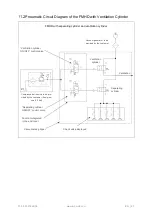
Страница 57: ...n cylinder Separating cylinder ON OFF control valve Ventilation cylinder ON OFF control valve Function integrated in the end cover Vacuum area gripper Check valve displayed Ventilation cylinder Separating cylinder Compressed air source to be pro vided by the customer flow pres sure 6 0 bar Vacuum generator to be provided by the customer Ventilation ...

Страница 58: ...inder and ventilation cylinder Blow off ON OFF control valve Separating cylinder ON OFF control valve Function integrated in the end cover Vacuum area gripper Check valve displayed Separating cylinder Compressed air source to be provided by the customer flow pressure 6 0 bar Vacuum generator to be provided by the customer ...

Страница 59: ...5 Product Declaration of Conformity 30 30 01 02574 For versions with ejector and dust filter Ejector instruction manual 30 30 01 01005 Dust filter instruction manual 30 30 01 00059 Compressed air source Optimum flowing compressed air pressure 6 0 bar Vacuum distribu tor Vacuum filter Hose clamps connector Vacuum Included in delivery Vacuum area gripper FMHD Vacuum generator ...

Страница 60: ...60 EN www schmalz com 30 30 01 01648 06 ...

Отзывы: