background image

Operating Modes

EN-US · 30.30.01.02084 · 02 · 12/20

21 / 72

6   Operating Modes

All the ejectors in the SCPSi-L series can be operated in two operating modes:

Via direct connection to inputs and outputs (standard I/O = SIO) or

Connection via a communication line (IO-Link)

By default, the ejector always runs in SIO mode, but it can be switched in and out of IO-Link mode by an
IO-Link master at any time.

6.1   SIO Operating Mode

In SIO mode, all input and output signals are connected to a controller, either directly or using intelligent
terminal boxes. For this purpose, in addition to the supply voltage, two input signals and one output sig-
nal should be connected to allow the ejector to communicate with the controller.

The following basic ejector functions are used:

Inputs

– Suction ON/OFF

– Blow off ON/OFF

Output

– Feedback 2 (“Part Present” check)

The “Blow off” signal does not have to be used if the ejector is operated with internal time control in
blow off mode. This allows operation on a single port in a configurable terminal box (using 1xDO and
1xDI).

The parameters are set and the internal counters are read out using the operating and display elements.

The energy and process control functions are unavailable in SIO mode.

6.2   IO-Link Operating Mode

When operating the ejector in IO-Link mode (digital communication), the supply voltage, the ground and
the communication line are connected to a controller, either directly or using intelligent terminal boxes.
The communication line for IO-Link (C/Q line) is always connected with an IO-Link master port (point-to-
point connection). It is not possible to connect multiple C/Q lines to a single IO-Link master port.

Connecting the ejector via the IO-Link provides access to a number of additional ejector functions along-
side the basic functions of suction, blow off, feedback, etc. They include:

The current vacuum level

Selection of four production profiles

Errors and warnings

Ejector system status display

Access to all parameters

Functions for energy and process control

So that all the modifiable parameters can be read directly via the higher-level controller, modified and
written back to the ejector.

Evaluation of the condition monitoring and energy monitoring results allows you to draw direct conclu-
sions regarding the current handling cycle and perform trend analysis. The ejector supports the IO-Link re-
vision 1.1 with four bytes of input data and two bytes of output data. It is also compatible with IO-Link
masters that use the 1.0 revision. In this case, one byte of input data and one byte of output data are sup-
ported. The exchange of process data between the IO-Link master and the ejector is cyclical. Parameter
data (acyclical data) is exchanged by the user program in the control unit using communication modules.

Содержание 10.02.02.05827

Страница 1: ...Compact Ejector SCPSi L Operating Instructions WWW SCHMALZ COM EN US 30 30 01 02084 02 12 20 ...

Страница 2: ...lished thereby Repro duction of the contents in full or in part is only permitted within the limits of the legal provisions of copyright law Any modifications to or abridgments of the document are prohibited without explicit writ ten agreement from J Schmalz GmbH Contact J Schmalz GmbH Johannes Schmalz Str 1 72293 Glatten Germany T 49 7443 2403 0 schmalz schmalz de www schmalz com Contact informat...

Страница 3: ...Technical Data 13 4 1 Display Parameters 13 4 2 General Parameters 13 4 3 Electrical Parameters 13 4 4 Factory Settings 14 4 5 Performance Data 15 4 6 Dimensions 15 4 7 Pneumatic Circuit Plans 16 5 Operating and Menu Concept 17 5 1 Enabling the Menu 17 5 2 Individual Functions 17 5 3 Main Menu 18 5 4 Configuration Menu 18 5 5 System Menu 20 6 Operating Modes 21 6 1 SIO Operating Mode 21 6 2 IO Lin...

Страница 4: ...uction Setup Profiles 32 7 24 Error Display 32 7 25 Energy and Process Control EPC 33 7 25 1 Condition Monitoring CM 33 7 25 2 Energy Monitoring EM 35 7 25 3 Predictive Maintenance PM 36 7 25 4 Diagnostic Buffer 37 7 25 5 EPC Data Buffer 37 7 25 6 EPC Values in the Process Data 37 8 Transport and Storage 39 8 1 Checking the Delivery 39 9 Installation 40 9 1 Installation Instructions 40 9 2 Mountin...

Страница 5: ...le 52 13 4 Opening and Cleaning the Ejector Module 53 13 5 Cleaning the Press in Screen 53 13 6 Replacement of the Device with a Parameterization Server 53 14 Warranty 55 15 Spare and Wearing Parts Accessories 56 15 1 Spare and wearing parts 56 15 2 Accessories 56 16 Decommissioning and Recycling 58 16 1 Disposing of the Ejector 58 16 2 Materials Used 58 17 Attachment 59 17 1 Overview of the Displ...

Страница 6: ...instructions in these Operating instructions may result in injuries ð Schmalz is not liable for damage or malfunctions that result from failure to heed these instructions If you still have questions after reading the technical documentation contact Schmalz Service at www schmalz com services 1 3 Type Plate The type plate 1 is permanently attached to the ejector at the location shown and must alway...

Страница 7: ...formation ü This symbol represents a prerequisite that must be met prior to an operational step 4 This symbol represents an action to be performed ð This symbol represents the result of an action Actions that consist of more than one step are numbered 1 First action to be performed 2 Second action to be performed ...

Страница 8: ...sonal protective equipment PPE when working in the danger zone CAUTION Depending on the purity of the ambient air the exhaust air can contain particles which escape from the exhaust air outlet at high speed Eye injuries 4 Do not look into the exhaust air flow 4 Wear eye protection 2 2 Intended Use The ejector is built in accordance with the latest standards of technology and is safe to operate upo...

Страница 9: ...ntially explosive atmospheres Use in medical applications Lifting people or animals Evacuation of objects that are in danger of imploding Ballistic applications 2 4 Personnel Qualifications Unqualified personnel cannot recognize dangers and are therefore exposed to higher risks 1 Task only qualified personnel to perform the tasks described in these Operating instructions 2 The product must be oper...

Страница 10: ... High Vacuum Nozzle size 2 07 2 09 2 13 2 16 3 16 3 20 Controller NO for normally open NC for normally closed Control RD for with control No specification for without control Electrical connection M12 5 connector Signal type for signal inputs and out puts NPN PNP 3 2 Ejector Structure 2 3 4 5 1 6 7 8 1 1 2 vacuum connection 2 Mounting hole 2x 3 Display and control element 4 M12 electrical connecti...

Страница 11: ...vacuum limit value H1 4 DOWN BUTTON 5 UP BUTTON 6 LED vacuum limit value H2 7 LED process state suction 8 LED process state blow off Definition of the LED Indicators The suction and blow off process states are each assigned an LED Display Ejector state LEDs both off No suction from ejector LED for the suction function is constantly lit Ejector is applying suction or in control mode LED for the blo...

Страница 12: ...limit values Their display is independent of the switching function and assignment of the output and independent of whether the condition monitoring function is active Display Ejector state LEDs both off Rising vacuum Vacuum H2 Falling vacuum Vacuum H2 h2 H2 LED lit steadily Rising vacuum Vacuum H2 and H1 Falling vacuum Vacuum H2 h2 and H1 h1 Both LEDs lit steadily Rising vacuum Vacuum H1 Falling ...

Страница 13: ...condensation Precision of vacuum sen sor 3 FS full scale Degree of protection IP65 Operating pressure flow pressure P 2 4 2 6 bar Operating medium Air or neutral gas 5 µm filtered with or without oil class 3 3 3 com pressed air quality in acc with ISO 8573 1 4 3 Electrical Parameters Parameter Symbol Limit values Unit Comment min typ max Supply voltage USA 22 8 24 26 4 V DC PELV1 Power consumption...

Страница 14: ...ating and therefore the destruction of the ejector 4 Mean value 4 4 Factory Settings Code Parameter Value of the factory setting X 1 Limit value H1 750 mbar h 1 Hysteresis value h1 150 mbar X 2 Limit value H2 550 mbar h 2 Hysteresis value h2 10 mbar XP1 Limit value H1 4 0 bar hp1 Hysteresis value hP1 0 2 bar tbL Blow off time 0 2 s ctr Control Activated on dc5 Continuous suction Deactivated off t ...

Страница 15: ...129 227 323 Max blow off capacity 1 l min 130 Air consumption 1 suction l min 22 45 71 98 102 172 Sound level1 unobstructed suction dBA 74 77 76 77 80 81 Sound level1 suction dBA 62 63 72 77 Weight kg 0 5 1 at 4 5 bar 4 6 Dimensions B B1 H H1 H3 Y1 Y2 X1 X2 17 6 37 5 95 75 109 56 5 35 28 40 28 G1 G2 G3 G4 L L3 L4 D d 1 4 inter nal thread 1 2 inter nal thread M12x1 ex ternal thread 5 pin M4 inter n...

Страница 16: ...Technical Data 16 72 EN US 30 30 01 02084 02 12 20 4 7 Pneumatic Circuit Plans SCPSi L NO SCPSi L NC ...

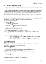
Страница 17: ...o enter the first digit of the PIN 3 Confirm using the button 4 Enter the remaining digits in the same way 5 To enable the device using the menu press the button The lock is activated again automatically after you leave the selected menu or close the function The PIN 000 must be set for permanent deactivation of the lock Tips and Tricks for Parameter Setting By pressing the or button for approx 3 ...

Страница 18: ...teresis value h 1 Hysteresis value for the control function x 2 Vacuum limit value H2 Part Present check switching value h 2 Hysteresis value h 2 Part Present check hysteresis value tbL Blow off time Only activated for E t or l t CAL Calibration Calibrate the vacuum sensor The factory settings for the parameters are listed in the Technical Data section 5 4 Configuration Menu An extended configurat...

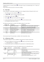
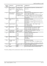
Страница 19: ...time can be set o 2 Signal output 2 no nc Configure output 2 Part Present check for normally open for normally closed tYP Signal Type PnP nPn Define signal type for inputs and outputs Signal type PNP input output on 24 V Signal type NPN input output on 0 V dLY H2 switching signal delay Values 10 50 200 and oFF Delays the switching signals X1 and X2 Unit milliseconds uni Vacuum unit bA ix PA Define...

Страница 20: ...seconds ð During activation 5 appears 2 The parameters are set in accordance with the description in the Main Menu section The following table shows an overview of the display codes in the system menu Display code Parameter Explanation cc1 Counter 1 Suction cycles cc2 Counter 2 Number of valve switches 5oC Software function Software on the internal controller Type Part number Format of the part no...

Страница 21: ...e digital communication the supply voltage the ground and the communication line are connected to a controller either directly or using intelligent terminal boxes The communication line for IO Link C Q line is always connected with an IO Link master port point to point connection It is not possible to connect multiple C Q lines to a single IO Link master port Connecting the ejector via the IO Link...

Страница 22: ...6 2 2 Parameter Data In addition to the process data that is exchanged automatically the IO Link protocol provides an acyclical data channel for identification data setting parameters or general feedback from the device The avail able data objects are referred to as ISDU with IO Link and are to be uniquely addressed within a device through their index and subindex Controller manufacturers usually ...

Страница 23: ...n signal is re ceived An integrated sensor records the vacuum generated by the venturi nozzle The exact vacuum level is shown on the display and can be read from the IO Link process data H1 H1 h1 H2 H2 h2 Vacuum mbar Vacuum on Time s OUT on OUT off The ejector has an integrated air saving function and automatically regulates the vacuum in suction mode The electronics switch the venturi nozzle off ...

Страница 24: ... mode in which the ejector is operated by the system controller The operating mode may be changed from automatic to manual mode using the buttons The ejector is always parameterized in automatic mode 7 3 2 Manual Operating Mode WARNING Through an external signal manual operation is exited external signals are evalu ated and system parts move Personal injury or damage to property due to collisions ...

Страница 25: ...eactivated 4 Set the corresponding value using bit 2 in the output process data byte PDO A change to bit 0 or bit 1 suction or blow off in the PDO also causes the ejector to exit setting mode This function is only available in IO Link mode 7 4 Vacuum Monitoring The ejector has an integrated sensor for monitoring the current system vacuum The vacuum level pro vides information about the process and...

Страница 26: ...an deactivate the automatic control shutoff The function can be set under the dC5 menu item in the configuration menu or via IO Link If the dC5 oFF function is selected the ejector switches to the Continuous suction operating mode when there is excessively high leakage and the valve switches too frequently With the dC5 on set ting continuous suction is deactivated and the ejector continues in cont...

Страница 27: ...tches to the pneumatically OFF operating state 7 8 Evaluating the Inlet Pressure The available supply pressure level in the system cannot be measured by the ejector itself However the current measured value for the inlet pressure can be transmitted to the ejector from the system controller via IO Link In this case the ejector evaluates the pressure level and activates a condition monitoring warnin...

Страница 28: ...al output is switched on or off when the system vacuum is higher or lower than the relevant threshold value The output type parameter can be used to switch between PNP and NPN The signal inputs are also con figured with this function This setting can be switched using the tYP menu item in the configuration menu or via IO Link 7 11 Signal Type The signal type or the switching behavior PNP or NPN of...

Страница 29: ... off delay can be set with the parameter dlY in the configuration menu or via IO Link The value can be set to 10 50 or 200 ms To deactivate this function enter the value 000 off The switch off delay affects the OUT2 discrete output the process data bit in IO Link and the H2 status dis play If the OUT2 output is configured as a normally open contact no there will be an electrical switch off delay O...

Страница 30: ... parameter values using the user menu or IO Link You can also prevent the use of the Data storage mechanism de scribed in IO Link Standard V1 1 Bit Meaning 0 Parameter write access locked Parameters cannot be changed via IO Link 1 Data storage locked Data storage mechanism is not triggered 2 Local parametrization locked Parameters cannot be changed via the user menu Coding for the device access lo...

Страница 31: ...1 cc1 Counter for suction cycles suc tion signal input Counter 2 cc2 Counter for the suction valve switching frequency Displaying a Counter on the Operating Panel of the Ejector ü Select the counter you wish to see in the system menu 4 Confirm the counter by pressing the button ð The last three decimal places of the counter total are displayed the digits x100 This corresponds to the least signific...

Страница 32: ...ck 0 48 61 8 593 The serial number in this example is 48 618 593 4 To exit the function press the button 7 23 Production Setup Profiles The ejector can store up to four different production setup profiles P 0 to P 3 via IO Link All the impor tant parameter data for handling the workpiece is stored in this case The profiles are selected using the PDO byte 0 process data byte This gives users a quic...

Страница 33: ...and suction off states very frequently The number of valve switch ing procedures thus increases rapidly within a short time To protect the ejector and increase its service life the ejector switches the air saving function off automatically at a switching frequency of more than 6 times every 3 seconds and activates continuous suction the ejector then remains in the suction state In IO Link mode the...

Страница 34: ...s Evacuation times t0 and t1 Vacuum mbar Suction ON Time s If the measured evacuation time t1 from H2 to H1 exceeds the specified value t 1 the Evacuation time longer than t 1 condition monitoring warning is triggered and the system status light switches to yellow The specified value for the max permitted evacuation time can be set under the t 1 menu item in the configuration menu or via IO Link S...

Страница 35: ...w Leakage level evaluation This function determines the average leakage during the last suction cycle divides it into subareas and makes it available as a parameter via IO Link Autoset The CM Autoset IO Link function in the process output data allows the condition monitoring parameters for maximum permitted leakage L and the evacuation time t 1 to be set automatically The ac tual values from the l...

Страница 36: ...ete Measurement of dynamic pressure This measures the system vacuum achieved during unobstructed suction The duration of the measure ment is approx 1 second Therefore to evaluate a valid dynamic pressure uninterrupted suction is re quired for at least 1 second after starting the suction i e the suction point must not be covered by a part Measured values below 5 mbar or above the vacuum limit value...

Страница 37: ... processes in the system The contents of the EPC data buffer can be read out via an IO Link parameter See the associated IO Link Data Dictionary for the actual data display of this buffer The con tents of the memory remains intact after a power failure 7 25 6 EPC Values in the Process Data To quickly and easily capture the most important results from the condition monitoring CM energy monitoring a...

Страница 38: ... control system 4 Switch back to EPC Select 00 5 Wait until the EPC Select Acknowledge bit from the device is reset to 0 6 Proceed in the same way for the next value pair e g EPC Select 10 The following diagram illustrates the sequence for the EPC system query 00 01 00 00 10 11 Pressur e Pressur e Pressur e Pressur e CM Leakage Voltage Vacuum Evac Time Vacuum Dynamic pressure Vacuum Air cons Vacuu...

Страница 39: ...ivery can be found in the order confirmation The weights and dimensions are listed in the delivery notes 1 Compare the entire delivery with the supplied delivery notes to make sure nothing is missing 2 Damage caused by defective packaging or occurring in transit must be reported immediately to the carrier and J Schmalz GmbH ...

Страница 40: ...e is in an idle depressurized state 3 Pneumatic and electrical line connections must be securely connected and attached to the ejector 9 2 Mounting The ejector may be installed in any position There are two 4 3 mm mounting holes for mounting the ejector When mounting with fastening screws use M4 washers 2 Nm max tightening torque For the start of operations the ejector must be connected to the con...

Страница 41: ...se pollution due to incorrect installation of the pressure and vacuum connec tions Hearing damage 4 Correct installation 4 Wear ear protectors 9 3 1 Connecting the Compressed Air and Vacuum 1 2 1 Compressed air connection 2 Vacuum connection The 1 4 thread compressed air connection is marked with the number 1 on the ejector 4 Connect the compressed air hose The max tightening torque is 4 Nm The 1 ...

Страница 42: ...l diameter has the dimensions required for the ejector to achieve its performance data On the vacuum side ensure that the internal diameter has the necessary dimensions for preventing high flow resistance If the selected internal diameter is too small the flow restrictor and the evacu ation times increase and the blow off times are extended The following table shows the recommended line cross sect...

Страница 43: ... constant load currents 0 1 A The electrical connection is established using a 5 pin M12 connector that supplies the vacuum switch with voltage and contains the two input signals and the output signal The inputs and outputs are not electri cally isolated from one another The maximum line length for the supply voltage the signal inputs and the signal output is 30 m in SIO mode 20 m in IO Link mode ...

Страница 44: ...ue GNDS A Ground for sensors actuators 4 Black C Q IO Link communication 5 Gray 1 When using Schmalz connection cable part no 21 04 05 00080 9 5 Start of Operations A typical handling cycle is divided into the following three phases pickup blowoff and idle To check whether sufficient vacuum has built up the limit value H2 is monitored by an integrated vacuum sensor during suction and output to the...

Страница 45: ...ormed only by specialists who can evaluate the effects of signal changes on the overall system WARNING Extraction of hazardous media liquids or bulk material Personal injury or damage to property 4 Do not extract harmful media such as dust oil mists vapors aerosols etc 4 Do not extract aggressive gases or media such as acids acid fumes bases biocides dis infectants or detergents 4 Do not extract l...

Страница 46: ...ion cycle The diagrams also indi cate the times at which EPC measured values are updated Handling cycle with dynamic pressure measurement and average leakage Typical suction cycle Vacuum SUCTION BLOW OFF NEUTRAL SUCTION t Condition monitoring Evacuation time t0 Evacuation time t1 Dynamic pressure Leakage Air consumption El energy consumption ...

Страница 47: ...RAL SUCTION t Condition monitoring Evacuation time t0 Evacuation time t1 Dynamic pressure Leakage Air consumption El energy consumption Handling cycle with leakage L and readjustment Typical suction cycle Vacuum SUCTION BLOW OFF NEUTRAL SUCTION t Condition monitoring Evacuation time t0 Evacuation time t1 Dynamic pressure Leakage Air consumption El energy consumption ...

Страница 48: ...n Leakage Dynamic pressure Evacuation time t1 Evacuation time t0 Condition monitoring t SUCTION NEUTRAL BLOW OFF SUCTION Vacuum Handling cycle with excessive evacuation time t1 Typical suction cycle Vacuum Condition monitoring Evacuation time t0 Evacuation time t1 Dynamic pressure Leakage Air consumption El energy consumption SUCTION BLOW OFF NEUTRAL SUCTION t ...

Страница 49: ...ck the compressed air supply Ejector is faulty 4 Check the ejector and contact Schmalz Service if necessary Vacuum level is not reached or vacuum is created too slowly Press in screen in contami nated 4 Replace screen Silencer is dirty 4 Replace silencer insert Hose or screw unions are leaking 4 Replace or seal compo nents Leakage at suction cup 4 Eliminate leakage from suction cup Operating press...

Страница 50: ...o high E18 Input pressure outside operating range FFF Present vacuum exceeds the measurement range FF Overpressure in vacuum circuit this normally happens exclusively in blow off mode Error codes in SIO mode The error E01 remains on the display after being shown once Delete the error by switching off the power supply If this error occurs again after the power supply is switched back on then the de...

Страница 51: ...lly deleted when the device is switched on and is updated when a dynamic pressure value is detected Bits 5 and 7 are regularly updated independently of the suction cycle and reflect the current values for the supply voltage and system pressure The values measured by the condition monitoring system namely the evacuation times t0 and t1 and the leakage value L are reset at the beginning of the sucti...

Страница 52: ...ork 4 Secure it so that it cannot be switched back on 4 The ejector must only be operated with a silencer and press in screens 13 2 Cleaning the Ejector 1 For cleaning do not use aggressive cleaning agents such as industrial alcohol white spirit or thin ners Only use cleaning agents with pH 7 12 2 Remove dirt on the exterior of the device with a soft cloth and soap suds at a maximum tempera ture o...

Страница 53: ...e IO Link master mirrors all setting parameters for the device in a sepa rate non volatile memory When a device is swapped for a new one of the same type the setting parame ters for the old device are automatically saved in the new device by the master ü The device is operated on a master with IO Link version 1 1 or higher ü The Data storage feature in the configuration of the IO Link port is acti...

Страница 54: ...Maintenance 54 72 EN US 30 30 01 02084 02 12 20 Use the Parameterization server function of the IO Link master to ensure that no data is lost when switching the device ...

Страница 55: ...e are original parts supplied by us We are not liable for any damage resulting from the use of non original spare parts or accessories The exclusive use of original spare parts is a prerequisite for the proper functioning of the ejector and for the validity of the warranty Wearing parts are not covered by the warranty Opening the ejector will damage the tested labels This voids the warranty ...

Страница 56: ... W Spare part S 4 When tightening the fastening screws on the silencer module observe the maximum tightening torque of 0 5 Nm When you replace the silencer insert we recommend that you also replace the insulating plate 15 2 Accessories Part no Designation Note 21 04 05 00211 Connection cable M12 5 pin socket to 5 pin M12 connector 2 m 21 04 05 00080 Connection cable M12 5 pin with open end 5 m 21 ...

Страница 57: ...Spare and Wearing Parts Accessories EN US 30 30 01 02084 02 12 20 57 72 Part no Designation Note 10 07 01 00126 VFT 1 2 internal thread 100 Vacuum cup filter replaceable filter ...

Страница 58: ...ommissioning 2 Observe the country specific guidelines and legal obligations for waste prevention and disposal 16 2 Materials Used Component Material Housing PA6 GF PC ABS aluminum alloy Inner components Aluminum alloy anodized aluminum alloy brass galvanized steel stainless steel PU POM Silencer insert Porous PE Screws Galvanized steel Seals Nitrile rubber NBR Lubrication Silicone free ...

Страница 59: ... active dc5 Deactivate auto con trol shutoff Suppresses the automatic valve protection function when set to YE5 Cannot be activated when Ctr off t 1 Evacuation time Set the maximum permitted evacuation time L Leakage value Set the maximum permitted leakage bLo Blow off function Menu for configuring the blow off function E External blow off Selection of externally controlled blow off J t Internal b...

Страница 60: ...tructions ful fills the following applicable EU directives 2014 30 EU Electromagnetic Compatibility 2011 65 EU RoHS Directive The following harmonized standards were applied EN ISO 12100 Safety of machinery General principles for design Risk assessment and risk reduction EN 61000 6 3 A1 AC Electromagnetic compatibility EMC Part 6 3 Generic standards Emission standard for residential commercial and...

Страница 61: ... there are warnings 7 ro IO Link V1 1 V1 0 Device is not working properly there are errors 7 0 ro IO Link V1 1 only EPC value 1 byte Holds 8bit value as selected by EPC Select see PD Out Byte 0 7 0 ro IO Link V1 1 only 7 0 ro IO Link V1 1 only IO Link Version 1 1 234 0x00EA 38 4 kBd COM2 3 5 ms 4 byte Access EPC value 2 word Holds 16bit value as selected by EPC Select see PD Out Byte 0 Device stat...

Страница 62: ...Last measured free flow vacuum 1 mbar 3 EPC value 1 Primary supply voltage 0 1 Volt EPC value 2 Air consumption of last suction cycle 0 1 NL 7 6 wo IO Link V1 1 V1 0 Select Production Profile content is 2 bit binary coded integer 0 Activate Production Setup Profile P0 1 Activate Production Setup Profile P1 2 Activate Production Setup Profile P2 3 Activate Production Setup Profile P3 7 0 wo IO Link...

Страница 63: ...ing unlocked 0 menu editing locked with pin code 69 0x0045 bLo 1 byte 0 2 rw 0 0 Externally controlled blow off E 1 Internally controlled blow off time dependent I t 2 Externally controlled blow off time dependent E t 71 0x0047 o 2 1 byte 0 1 rw 0 0 NO 1 NC 73 0x0049 tyP 1 byte 0 1 rw 0 0 PNP 1 NPN 75 0x004B dLY 1 byte 0 3 rw 1 0 Off 1 10ms 2 50ms 3 200ms 74 0x004A uni 1 byte 0 2 rw 0 0 mbar 1 kPa...

Страница 64: ...187 0x00BB 2 bytes 0 10 9999 rw 2000 188 0x00BC 2 bytes 1 999 rw 250 200 0x00C8 1 byte 0 2 rw 1 201 0x00C9 1 byte 0 1 rw 0 202 0x00CA 2 bytes 998 H1 H2 h1 rw 750 203 0x00CB 2 bytes H1 H2 h1 10 rw 150 204 0x00CC 2 bytes H1 h1 H2 h2 2 rw 550 205 0x00CD 2 bytes H2 2 h2 10 rw 10 206 0x00CE 2 bytes 100 9999 rw 200 207 0x00CF 2 bytes 0 10 9999 rw 2000 Hysteresis h1 Setpoint H1 Disable continuous suction...

Страница 65: ...ted by switching PD Out 0 Bits 2 and 3 simultaneously from 0 to 1 123 0x007B rES 1 byte 1 wo 1 Restore to factory defaults 40 0x0028 1 byte V1 0 4 bytes V1 1 ro Copy of currently active process data input 41 0x0029 1 byte V1 0 2 bytes V1 1 ro Copy of currently active process data output 64 0x0040 2 bytes ro Current vacuum level unit 1 mbar 66 0x0042 2 bytes ro Supply voltage as measured by the dev...

Страница 66: ...ro 0 no actual value 1 Leakage of last suction cycle is 200mbar s 2 Leakage of last suction cycle is between 133 200mbar s 4 Leakage of last suction cycle is between 67 133mbar s 8 Leakage of last suction cycle is 67mbar s 148 0x0094 2 bytes ro Time from start of suction to H2 unit 1 ms 149 0x0095 2 bytes ro Time from H2 to H1 unit 1 ms 155 0x009B 1 byte ro Air consumption of last suction cycle un...

Страница 67: ... 0x0083 228 bytes ro Newest 38 entries in the diagnostic buffer encoding see table below 132 0x0084 6 bytes ro Newest entry in the diagnostic buffer encoding see table below 133 0x0085 100 bytes ro Newest 10 entries in the EPC data buffer encoding see table below 134 0x0086 10 bytes ro Newest entry in the EPC data buffer saved at last autoset encoding see table below EPC data buffer all entries Qu...

Страница 68: ...eries 21 10 01 00065 02 29 08 2014 J Schmalz GmbH Aacher Straße 29 D 72293 Glatten Tel 49 0 7443 2403 0 Fax 49 0 7443 2403 259 info schmalz de Availability of EPC data during suction cycle J Schmalz GmbH 8 of 11 SCPSi Data Dictionary ...

Страница 69: ...or Description Encoding of Diagnostic Type Diagnostic Type Bytes 2 5 0x1207 0x1208 0x1404 Notification Vacuum sensor calibrated successfully Notification Diagnostic buffer cleared Notification Parameters restored to factory defaults 0x1403 0x1203 0x0207 0x1405 Notification Manual mode entered 0x1202 Errors 0x0405 Error E02 Internal Error Error E07 appeared Primary voltage US too low Data Format of...

Страница 70: ...e of operating range CM Warning disappeared Input pressure outside of operating range 0x0211 CM Warning Valve protection activated 0x1120 0x0120 CM Warning appeared Primary voltage US outside of optimal range CM Warning disappeared Primary voltage US outside of optimal range 0x1108 0x0110 CM Warning H1 not reached in suction cycle CM Warning disappeared Free flow vacuum H2 h2 but H1 0x1102 0x1104 ...

Страница 71: ...110 0x8C01 0x1800 0x1801 0x1802 Event type Vacuum calibration OK Vacuum calibration failed System pressure fault Notification Notification Warning Simulation active General malfunction General power supply fault Primary supply voltage over run Error Error Warning Warning Event code Event name Remark Internal error e g E01 E02 Primary supply voltage US too low Data Format of Single Entry ISDU 134 D...

Страница 72: ... J Schmalz GmbH EN US 30 30 01 02084 02 12 20 Subject to technical changes without notice ...

Отзывы: