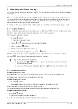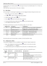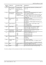
General Description of Functions
EN-US · 30.30.01.02084 · 02 · 12/20
27 / 72
Description
Explanation
The blow off signal overrides the suction signal, even if the specified
blow off time is very long.
The length of the blow off time [
tbL
] is set in the main menu. This menu item is suppressed in operating
mode [
-E-
].
The number displayed indicates the blow off time in seconds. Blow off times from 0.10 seconds to
9.99 seconds can be set.
7.7 Monitoring the Supply Voltages
The ejector measures the supply voltages U
S
. The measured value can be read from the parameter data.
If the voltages are outside the valid range (min. 19.2 V and max. 26.4 V), the following status messages
change:
•
Device status
•
Condition monitoring parameter
•
An IO-Link event is generated
There is no guarantee that the ejector will operate as intended below a supply voltage of 19.2 V:
•
The reaction to signal inputs is disabled.
•
The “Part Present” check output retains its normal functionality.
•
The current supply voltage can still be viewed using the
button.
•
The pneumatic state of the ejector changes as follows:
– For the NO-type ejector, the ejector switches to the “suction” operating state
– For the NC-type ejector, the ejector switches to the “pneumatically OFF” operating state
7.8 Evaluating the Inlet Pressure
The available supply pressure level in the system cannot be measured by the ejector itself. However, the
current measured value for the inlet pressure can be transmitted to the ejector from the system controller
via IO-Link. In this case, the ejector evaluates the pressure level and activates a condition monitoring
warning if the pressure level is not optimal. If there is a significant deviation, an error message is also gen-
erated.
A pressure level must also be transferred to enable the volume of compressed air consumed in the suction
cycle to be estimated in the area of energy monitoring.
7.9 Calibrating the Vacuum Sensor
As the production conditions for the internally integrated vacuum sensor can vary, we recommend cali-
brating the sensor once it is installed in the ejector. To calibrate the vacuum sensor, the system's vacuum
circuit must be open to the atmosphere.
The function for zero-point adjustment of the sensor is performed in the main menu under the parameter
CAL
or using IO-Link.
1. Press the
button
ð
The menu changes to input
2. Press the
or
button until
cal
appears on the display
3. Confirm with the
button
4. When
YE5
appears, press the
button to confirm.
ð
The vacuum sensor is now calibrated.
A zero offset is only possible in the range of ± 3% around the theoretical zero position.
Содержание 10.02.02.05827
Страница 1: ...Compact Ejector SCPSi L Operating Instructions WWW SCHMALZ COM EN US 30 30 01 02084 02 12 20 ...
Страница 16: ...Technical Data 16 72 EN US 30 30 01 02084 02 12 20 4 7 Pneumatic Circuit Plans SCPSi L NO SCPSi L NC ...
Страница 72: ... J Schmalz GmbH EN US 30 30 01 02084 02 12 20 Subject to technical changes without notice ...


