background image

1-800-810-WIRE • www.sargentlock.com • A7856C         9

Profile Series v.G1.5 Rim Exit Device     

Copyright © 2016, Sargent Manufacturing Company

, an ASSA ABLOY Group company

. All rights reser

ved. 

Reproductions in whole or in part without express written permission of Sargent Manufacturing Company is prohibited.

10/31/16

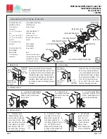
For exterior applications, use ET gasket (P/N 52-0263)  

to seal between ET escutcheon and outside door surface.
1A.  For wood doors: Route ET wire harness through the cylinder  


hole,  out the other side, and through the wire run channel to  


the controller cutout. 

1B.  For metal doors: Route ET wire harness  


through the cylinder hole and door  


and out the controller cutout. 

2.   Position and hold ET trim on the door.
3.    Connector from ET harness connects 

       to connector from chassis (Fig. 2)

6

Installation Instructions: 8877/8878 Rim Type Exit Device

Step #2 – Position Exit Trim (ET) 

Step #1 – Prepare Door

A. Verify Hand and Bevel of Door

•  This device is non-handed.
•  Door should be fitted and hung.
•  Verify box label for size of exit device and function.

Inside

Outside

Left Hand 

Reverse Bevel 

LHRB

Right Hand 

Reverse Bevel 

RHRB

Fig.  1

B. Door Preparation 

If using a mullion, install prior to installing hardware.
Doors should be pre-prepped. 
Prepare door according to appropriate template:

•  Exit installation instructions A6770
•  Door Manufacturer’s Template 4640 (Metal and Wood)

Note: Wood door has additional cutout if installation includes a cylinder.

Outside of Door

ET Wire Harness
(from motor)

Fig. 2

Exit trim

Exit trim Gasket 

(Exterior Applications)

Содержание v.G1.5

Страница 1: ...ufacturing Company an ASSA ABLOY Group company All rights reserved Reproduction in whole or in part without the express written permission of Sargent Manufacturing Company is prohibited Profile LK Exit Device Installation Instructions v G1 5 ...

Страница 2: ......

Страница 3: ... and can radiate radio frequency energy and if not installed and used in accordance with the instructions may cause harmful interference to radio communications However there is no guarantee that the interference will not occur in a particular installation If this equipment does cause harmful interference to radio or television reception which can be determined by turning the equipment off and on ...

Страница 4: ...ypad holds a total of 100 LK 2000 G1 LU G1 PK G1 PA G1 TU G1 TP G1 TA different user codes User codes 01 and 02 are utilized for Master and Supervisory Codes respectively SARGENT mortise locks are designed with quality components to provide high security performance and durability The Profile v G1 5 Series provides enhanced software and hardware features New v G1 5 controllers replace v G1 control...

Страница 5: ...of Sargent Manufacturing Company is prohibited 10 31 16 5 Parts Breakdown Items included with 8877 and 8878 Rim Exit Device Outside Escutcheon with Keypad Outside motorized ET Trim Assembly Exit Device Chassis Rail Assembly Rim cylinder for 8877 Inside Escutcheon with Circuit Board and Battery Pack 6 AA alkaline batteries Screw Packs 1 6 2 3 5 12 11 14 15 9 11 12 8 7 4 13 10 16 17 Outside Inside 8...

Страница 6: ...troller G1 TA G1 TP 68 1396 Inside Escutcheon Housing Only 1 52 0175 Inside Escutcheon End Cap Only 1 52 2441 100 User Controller Assembly LK 1 52 2783 2000 User Controller Assembly G1 LU 52 2784 2000 User Controller Assembly G1 PA G1 PK 52 2786 2000 User Key Pad Prox or Prox Only Controller Assembly w RF Technology G1 TA G1 TP 52 2785 2000 User Key Pad Only Controller Assembly w RF Technology G1 ...

Страница 7: ...ies v G1 5 Mortise Exit Device 10 31 16 Parts Breakdown continued Items included with 8977 and 8978 Mortise Exit Device Outside Escutcheon with Keypad Outside Motorized ET Trim Assembly Exit Device Chassis Rail Assembly and Mortise Lock Mortise Cylinder for 8977 Inside Escutcheon with Circuit Board and Battery Pack 6 AA alkaline batteries Screw Packs 1 6 2 8 3 5 4 16 17 11 12 13 10 7 14 15 19 Outs...

Страница 8: ...52 0175 Inside Escutcheon End Cap Only 1 52 2441 Enclosure Assembly LK 1 52 2783 Enclosure Assembly G1 LU 1 52 2784 Key Pad Prox or Prox Only Controller Assembly G1 PA G1 PK 1 52 2786 2000 User Key Pad Prox or Prox Only Controller Assembly w RF Technology G1 TA G1 TP 1 52 2785 2000 User Key Pad Only Controller Assembly w RF Technology G1 TU 1 3 52 0170 Battery Cover 1 52 2309 Battery Cover RF Tech...

Страница 9: ...utout 2 Position and hold ET trim on the door 3 Connector from ET harness connects to connector from chassis Fig 2 6 Installation Instructions 8877 8878 Rim Type Exit Device Step 2 Position Exit Trim ET Step 1 Prepare Door A Verify Hand and Bevel of Door This device is non handed Door should be fitted and hung Verify box label for size of exit device and function Inside Outside Left Hand Reverse B...

Страница 10: ... 1 4 20 x 2 3 8 flat head machine screws Correct Incorrect Fig 4C Step 4 Install Cylinder and Secure Chassis For devices without cylinder skip this step 1 Insert cylinder into ET control Fig 4A 2 Mate cylinder tailpiece into hub of exit device chassis 3 Make sure ET harness is clear of cylinder and cylinder tailpiece 4 Secure cylinder to exit chassis using 2 12 24 x 1 7 8 connecting screws Fig 4B ...

Страница 11: ...d doors require a fire stop plate on the outside of the door Fig 5A 1 Drill 2 1 8 x 1 1 4 deep holes in the door if not already present Refer to template for fire stop prep locations 2 Attach with flap up and out using 2 8 x 1 2 self tapping screws for wood and metal doors Fig 5A Step 6 Gasket Installation for Exterior Doors For exterior applications use a gasket between escutcheon and outside doo...

Страница 12: ...o Step 6 Before the controller is attached to the door 1 Attach the reader assembly ribbon cable to the inside face of the controller assembly side that faces towards the door when mounted Fig 8B Note Install ribbon cable with side marked TOP facing up Fig 8A 2 Attach the ground wire to the bottom of the controller assembly E1 Fig 8A 3 Connect the exit connector to the bottom of the controller TB1...

Страница 13: ...ty Screw Security Tool P N 01 0297 Included Battery Keeper Fig 9 Step 10 Install and Remove Batteries A Install Batteries and Keeper 1 Place 6 AA batteries into the compartment being careful to properly align polarity Fig 10A 2 To install battery keeper insert the tabs on the bottom of the keeper into the battery compartment slots and press the keeper tightly against batteries and inserting tabs i...

Страница 14: ...o Exit Installation Instructions A6770 Step 12 Install Rail Assembly For information about the RF Technology versions G1 TU G1 TP G1 TA refer to RF Technology Lock on page 21 For information about Wiring refer to Wiring Options starting on page 22 For information about the Testing refer to Operational Check on page 27 Tabs Fig 11 Retaining Slots Step 11 Install Inside Cover 1 Attach inside cover t...

Страница 15: ...lation all holes must be free of burrs debris and sharp edges Prepare door according to appropriate template Exit installation instructions A6770 Wood door template A7457 ships with product Door manufacturer s template 4641 metal and wood Through bolt Hole Outside Cylinder Hole 76 and 78 Functions Lever Handle Hole Pre drilled and or Tapped Holes 2 places Mortised Pocket Hole for Ribbon Cable from...

Страница 16: ...ns use ET gasket 52 0263 to seal between ET escutcheon and outside door surface Fig 2A 2 Slide mortise lock into door and securely fasten with 2 flat head screws Fig 2B 3 Route ET harness through square wire cutout and out other side of door 4 Place ET control on door with spindle inserted through mortise lock Fig 2A Step 2 Install ET Exit Trim and Mortise Lock Fig 2B Outside of Door Showing Wood ...

Страница 17: ...tion of mortise lock Fig 3B 4 Secure chassis and ET with 2 1 4 20 x 2 3 8 flat head machine screws Fig 3A 4 Fasten exit chassis to door using 4 10 wood screws for wood doors or 4 10 24 machine screws for metal doors Correct Incorrect Fig 4C Step 4 Install Cylinder and Secure Chassis For devices without cylinder skip this step 1 Insert cylinder into ET control Fig 4A 2 Mate cylinder tailpiece into ...

Страница 18: ...Gasket Installation for Exterior Doors For exterior applications use a gasket between escutcheon and outside door surface 1 Carefully remove the backing from the gasket 2 Apply gasket to escutcheon carefully a Starting in one place press the adhesive side of the gasket firmly against the escutcheon b Work around the escutcheon pressing the sticky side of the gasket firmly against the escutcheon ed...

Страница 19: ...r to Step 6 Before the controller is attached to the door 1 Attach the reader assembly ribbon cable to the inside face of the controller assembly side that faces towards the door when mounted Fig 8B Note Install ribbon cable with side marked TOP facing up Fig 8A 2 Attach the ground wire to the bottom of the controller assembly E1 Fig 8A 3 Connect the exit connector to the bottom of the controller ...

Страница 20: ...rew Security Tool P N 01 0297 Included Battery Keeper Step 10 Install and Remove Batteries A Install Batteries and Keeper 1 Place 6 AA batteries into the compartment being careful to properly align polarity Fig 10A 2 To install battery keeper insert the tabs on the bottom of the keeper into the battery compartment slots and press the keeper tightly against batteries and inserting tabs into bottom ...

Страница 21: ...ock in next section For information about Wiring refer to Wiring Options starting on page 21 For information about the Testing refer to Operational Check on page 26 Installation for the RF Technology Lock for G1 TU G1 TA G1 TP is for the most part installed as described in section 6 In addition The antenna board must be carefully moved to access the upper through bolt screw Care should be taken to...

Страница 22: ...door manufacturer when specified during ordering process 2 Wiring to pigtail harness is per facility wiring requirement ElectroLynx connector terminations and wire colors all match 3 If door does not have an ElectroLynx type door harness cut connectors off product and hard wire or consult factory for appropriate mating harness ElectroLynx As part of their promise to provide innovative fast and eff...

Страница 23: ...utch eon along the battery keeper back under the bottom opening between the controller and escutcheon and attach at the bottom of the controller Note Connectors go on only one way Do not offset connectors and make sure they are completely seated A A B C D Fig 1 ElectroLynx Lock Wire Connections Door Position Switch DPS Install the SARGENT 3287 Door Status Switch according to instructions included ...

Страница 24: ...ss and hard wire to non ElectroLynx two conductor door harness b DM requires two conductors c Hard wire door harness to power transfer device d Hard wire door status switch to power transfer device Fig 2 Forced Propped Door Connector J4 Forced Propped Door Option ElectroLynx Wiring System Door Status Switch Wire for switch contact closure when door is opened Typical locations shown in Fig 1 QC4A E...

Страница 25: ...quires two conductors c Hard wire door harness to power transfer device d Hard wire door status switch to power transfer device IMPORTANT 6 AA batteries MUST be removed from controller when using 3267 power supply Ground Tab E3 TB2 Remote Power Unlock Connector TB1 Motor Connector Door Inside Escutcheon Outside Escutcheon A Note Refer to 3267 Power Supply Instruction Sheet A7477 Fig 3A Remote Powe...

Страница 26: ...s to power transfer device d Hard wire door status switch to power transfer device IMPORTANT 6 AA batteries MUST be removed from controller when using 3267 power supply Ground Tab E3 TB2 Remote Power Unlock Connector TB1 Motor Connector Door Inside Escutcheon Outside Escutcheon A Note Refer to 3267 Power Supply Instruction Sheet A7477 Fig 3A Remote Powering and Remote Unlocking ElectroLynx Wiring ...

Страница 27: ...any is prohibited Profile Series v G1 5 LK Exit Device 10 For devices with cylinders insert key into cylinder and rotate Check to see if 1 The key retracts the latch if applicable Key should rotate freely 2 Depress inside rail to retract latch 3 Enter 1234 to unlock outside lever handle and retract latch 4 If the lock is prox only G1 PA or RF Technology with Prox G1 TA refer to keypad programming ...

Страница 28: ...ovation and replacement applications The company s customer base includes commercial construction institutional and industrial markets Copyright 2016 Sargent Manufacturing Company an ASSA ABLOY Group company All rights reserved Reproduction in whole or in part without the express written permission of Sargent Manufacturing Company is prohibited ASSA ABLOY is the global leader in door opening solut...

Отзывы: