10/31/16
1-800-810-WIRE • www.sargentlock.com • A7856C 23
Copyright © 2016, Sargen
t Manufacturing Company
, an A
SS
A AB
LO
Y G
roup company
. All right
s reser
ved
.
Reproductions in whole or in par
t without express writ
ten permission of Sargen
t Manufacturing Company is prohibited
.
Profile Series v.G1.5/LK Exit Device
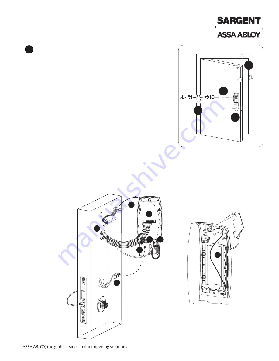
Before the controller is attached to the door (Fig. 1A):
1. Attach the reader cable to the controller.
2. Attach the connector from the lock into the bottom
of the circuit board (TB2, Fig. 3B).
3. Plug the ground wire into the bottom of the controller assembly (E1, Fig. 3B).
4. Route the connector from the raceway through the top opening between the controller and the escutch-
eon, along the battery keeper, back under the bottom opening between the controller and escutcheon and
attach at the bottom of the controller.
Note: Connectors go on only one way.
Do not offset connectors and make sure they are completely seated.
A
A
B
C
D
Fig. 1
ElectroLynx Lock Wire Connections
Door Position Switch (DPS)
Install the SARGENT 3287 Door Status Switch according to
instructions included in the kit.
Wire the 3287 Door Status Switch to the ElectroLynx frame har-
ness and to the door status wires:
1. Connect the common wire of the switch to the common wire
of the harness.
2. Connect the normally open wire of the switch to the door
position wire of the harness.
Note: The third wire (normally closed) of the 3287 Door
Status Switch is not used for this type of system.
Inside
Escutcheon
(Back)
Inside of Door
1
1
2
3
4
4
4
2
Inside
Escutcheon
(Front)
Fig. 1A
Содержание v.G1.5
Страница 2: ......


