


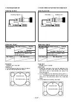


1 1 . Y FM Carrier Frequency Adjustment (Hi8)
[Connection]
VR1 05
�
TP1 41
0
TP1 91
[Adjustment
I
Check]
Measuring Point
Measuring Equipment
TP1 91 (CH 1 )
Oscilloscope
TP1 41 (GND)
Frequency counter
Condition
Record
Input Signal
I
Alignment Tape
No signal
ADJ. Location
ADJ. / Check Value
VR1 05
5.97
±
0.05 MHz
Preparation :
• POWER switch: "CAMERA"
• Stand-by switch: "STAN DBY"
• Set the Hi8 mode.
• Short pin @ , pin @ and pin @ of J 1 005.
Adjusting
I
Checking method:
1 . Adjust with VR1 05 to 5.97 ± 0.05 M Hz.
5.97 ± 0.05 M Hz
1 2. Y FM Deviation Adjustment (Hi8)
[Connection]
TP1 05
TP1 51
VR1 06
�
TP1 41
0
0CH2
[Adjustment
I
Check]
Measuring Point
Measuring Equipment
Condition
TP1 51 (CH 1 )
Oscilloscope
Record and
TP1 05 (EXT)
Hi8M P (ME) type tape
Playback
TP1 41 (GN D)
Input Signal
I
Alignment Tape
Color bar (Y signal only)
ADJ. Location
ADJ. / Check Value
VR1 06
1 .00 ± 0.05 Vp-p
Preparation:
• Short pin @ , pin @ and pin @ of J 1 005 .
• Set the Hi8 mode.
I
An AV cord should be connected, and
the video output terminal should be terminated at 75
Q .
Adjusting
I
Checking method:
1 . Record the color bar Y signal.
2. Play back the recorded signal.
3. Check the playback level.
It should be within 1 .00 ± 0.05 Vp-p.
4. When the level does not meet the specification, turn
VR1 06 as follows, and repeat 1 . to 3.
Counterclockwise ((")): When larger than specified value
Clockwise (()): When smaller than specified value
�
1 .00 ± 0.05 Vp-p
- 5-20 -


