


6. SYSTEM CONTROL CI RCUIT
6-1 . OUTLINE
6-1 -1 . Composition and Functions
For the composition of the whole of the system control, refer
to the block diagram.
The system control circuit is designed around the following
microprocessor.
Main controller IC351 (CXP80724) (CP1 board)
The main controller performs the following functions:
1 . Operation key-in
2. Character display on the screen
3. Clock control
4. Power ON and OFF
5. Backup of clock and counter data
6.
Mode control: Control of the operation mode for the
whole system
7. Mechanism control: Detection of the mechanism condi
tion and sequence control for the loading and capstan
motors
8. Circuit system control: Control of video, audio and
camera circuits
CAMERA CS
SCK
VIDEO CS
Main controller
SCK
CXP80724
so
LANC CS
9. Servo control: Servo control for drum motor and tape
travel control by means of capstan motor
For more information about the servo control, refer to the
next section.
6-1 -2. Inner Bus Communication
The system control circuit controls the entire deck by
detecting key-in operations and the condition of the
mechanism and the signal circuit system. The information
which is input from all of the sensors is read by the main
controller and processed, after which it is output as
operation mode setting information to mechanisms such as
the motor, signal processing circuits such as the video,
audio and camera signal processing circuits, and display
units such as the viewfinder.
In addition to the parallel signal line, bus lines for serial
transmission are provided for transmission of information
between the main controller and the various signal pro
cessing circuits.
Camera
microprocessor
Video IC
CXA1 207
SCK
LANC Controller
ATF IC
SI
M50721
XR1 082
ATF CS
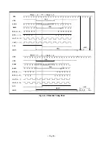
Fig. 6-1 . Inner Bus Communication System
Inner Bus
Clock Output
Data Length Per Fleld
CD
Main controller - ATF IC
Main controller
2 bytes
®
Main controller - Camera microprocessor
Camera microprocessor
2 bytes
®
Main controller
<-->
LANC controller
LANC controller
4 bytes
@
Main controller - Video IC
Main controller
3 bytes
Table 6-1 . Inner Bus Signal Specifications
- 4-3 1 -


