


6-2-4. LANC Operation During Program Editing
When carrying out program editing using the 8 mm VTR
camcorder, control of the external commander cannot be
carried out by the LANC terminal described in 6-2-3. When
carrying out editing operations, a VCR with a LANC terminal
is controlled (alternate recording and pausing operations) to
do the editing.
During editing (while the program No. is being displayed),
Pin @ of IC351 is set to Low, and Pin @ of IC334 and Pin
@ of IC336 switch to Low, and editing is carried out.
When Pin @ of IC336 is set to Low, power is not supplied to
the external commander.
Note:
When the program No. mark is not being displayed,
errors in operation may occur if the VCR with LANC
terminal is connected to the camcorder with a LANC
cable.
6-3. DISPLAY CONTROL
Various characters are displayed on the viewfinder to
display the operation mode of the deck. Display forms and
the contents shown on the screen are summarised in a
table in section 6-1 0.
For additional information, refer to the "Instruction Manual"
also.
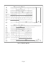
6-3-1 . Screen Character Generator Circuit
To display characters on the screen, the display control
data is transmitted from the main controller via the serial
bus to the character generator circuit where character
signals are generated. The character signals generated are
superimposed onto the video signal in the video circuit.
The video signal (VF VIDEO) is input to Pin @ of IC345 and
is separated into a vertical sync signal and a horizontal sync
signal inside the IC. The vertical sync signal is output from
Pin <J) , and the JOG VD (quasi vertical sync signal) output
from the main controller is substituted with the JOG H signal
(High in special playback mode) and input to Pin ® of
IC342.
In addition, the horizontal sync signal is output from Pin ®
of IC345 and input to Pin @ of IC342, where it becomes the
reference signal for generating the character signal.
The character signals and the fringe signal of the characters
to be superimposed onto the video signal are generated
inside IC342 in accordance with the serial data (Pi n @ input)
transmitted from the main controller.
Character signals consist of signals used for displaying
information such as the operation mode in the viewfinder or
on a
TV
monitor, and also signals for displaying information
such as date and time, which are recorded on the tape.
IC342 has two systems for outputting the character signal.
Signals for displaying and signals for recording are output
from separate terminals. Data for recording (CG REC
DATA) and its fringe signal (CG REC BLNK) are output
from Pin @ and Pin
@
respectively. Data for displaying and
its fringe signal are output from Pin @ and Pin @ respec
tively, and are output via the AN D gate IC341 as the data
for displaying in the viewfinder (CG DISP DATA) , the data
for displaying on the
TV
monitor screen (OS DISP DATA)
and the fringe signal (OS DISP BLNK).
IC342
µ PD6456
ON SCREEN 6
IC351
CXP80724
VIDEO
CHA1
BLN1
CHARACTER
GENERATOR
OS POSITION
ADJ
Fig. 6-2. Screen Character Generator Circuit
- 4-33 -
OS DISP DATA
IC341
µC74H C08A
ON
SCREEN
DISPLAY


