VCR Deck Operating Description
Samsung Electronics
8-9
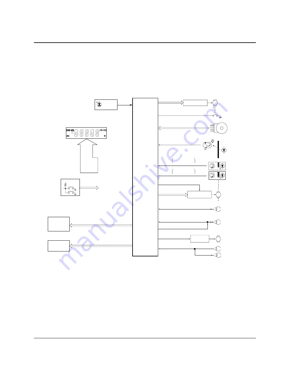
Fig. 8-11 System Control Block Diagram
8-5 System Control
In the VCR, complex mechanism, video, audio, servo circuits, etc. must be operated in specified timings matched
each other. The system control circuit performs entire controls for the VCR.
An automatic stop function is also provided to protect important tape if a trouble occurs on the complex mecha-
nism and the electrical circuits.
For this purpose, status of each part of the mechanism is always monitored with various sensor switches, and the
microcomputer controls collectively the unit so that the best condition is kept.
Moreover, the microcomputer controls signal switchings for each circuit according to the mechanism status.
Remote
control
Remote
Main microcomputer
Loading motor drive
broken safety tab
Tape stsrt sensor
Take up
Supply
Stsrt sensor
Tape
Mode sensor
(Detecting of mechanical mode position)
(Detection of cassette-in/cassette-out)
Loading motor control
(Voltage, direction)
Capstan motor control
(Speed direction)
Abnormal reel retation
FF/REW speed control
Loading motor
REC-inhibition
Mode SW
Tape end LED
Capstan motor
FG
PG
FG
Control
Cylinder motor
FG/PG pulse
Cylinder motor control
REC control
FG pulse
Current control
CTL pulse
(Linear time counter)
Cylinder
motor drive
Capstan
motor drive
T reel
sensor
S reel
sensor
Key matrix
Front button
Input
IIC BUS
AUDIO
VIDEO
TUNER
POWER ON/OFF
REC mute
TV/VCR
M
M
M
Abnormal reel retation
FF/REW speed control
STEREO
Содержание SV-DVD40
Страница 82: ...Circuit Operating Descriptions 7 7 Fig 7 12 Block Diagram ...
Страница 116: ...Circuit Operating Descriptions 7 41 3 Block Diagram Fig 7 38 LA70100M Block Diagram ...
Страница 141: ...VCR Deck Operating Description 8 12 Samsung Electronics Fig 8 14 Mecha Timing Chart ...
Страница 156: ...Samsung Electronics 11 1 11 Wiring Diagram ...
Страница 158: ...Schematic Diagrams 12 2 Samsung Electronics 6 1 S M P S ...
Страница 159: ...Schematic Diagrams Samsung Electronics 12 3 6 2 Power Drive ...
Страница 160: ...Schematic Diagrams 12 4 Samsung Electronics DT701 6 3 Display Function ...
Страница 161: ...Schematic Diagrams Samsung Electronics 12 5 6 4 System Control Servo ...
Страница 162: ...Schematic Diagrams 12 6 Samsung Electronics 6 5 A V ...
Страница 163: ...Schematic Diagrams Samsung Electronics 12 7 6 6 Hi Fi ...
Страница 164: ...Schematic Diagrams 12 8 Samsung Electronics 6 7 A2 NICAM ...
Страница 165: ...Schematic Diagrams Samsung Electronics 12 9 6 8 SECAM Option ...
Страница 166: ...Schematic Diagrams 12 10 Samsung Electronics 6 9 OSD VPS PDC ...
Страница 167: ...Schematic Diagrams Samsung Electronics 12 11 6 10 TM ...
Страница 168: ...Schematic Diagrams 12 12 Samsung Electronics 6 11 Input Output ...
Страница 169: ...Schematic Diagrams Samsung Electronics 12 13 6 12 DVD AV Decoder ...
Страница 170: ...Schematic Diagrams 12 14 Samsung Electronics 6 13 DVD Servo ...
Страница 171: ...Schematic Diagrams Samsung Electronics 12 15 6 14 DVD Audio Video ...


