Circuit Operating Descriptions
7-25
(3) Chroma Signal Recording System
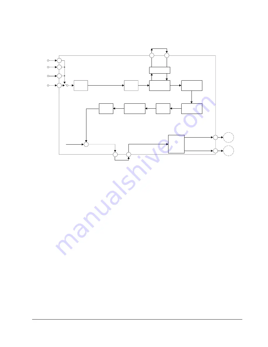
Fig. 7-23 Chrominance Record Process
AV V IN
IC301 LA71750/30M
AUX V IN
TU V AT
VIDEO
AGC
LPF
YNR Y/C
COMB
CCD
4.43MHz
BPF
50
54
48
78
79
CANAL V IN
52
REC
CURRENT
AMP
SP H'D
1.3MHz
LPF
MAIN
CONVERTER
BURST
EMPHA
ACC
AMP
46
43
REC LUMINANCE
88
94
+
SLP H'D
1) Outline
Fig. 7-23 shows the chroma signal recording system. The chroma signal recording process is performed by video
IC. The input video signal is supplied to Y/C COMB circuit through AGC AMP.
The output signal of Y/C COMB circuit is applied to ACC amplifier. The ACC amplifier is used for both burst
ACC which keeps the burst level at a constant value in recording and the color ACC which controls the reference
level of the burst ACC with the color signal level. The color ACC works to maintain a relatively high output level
by boosting low level input signals to improve color S/N ratio. The signal is then applied to the burst emphasis
circuit. Burst emphasis emphasizes the burst signal by +6dB during recording and feeds it to the main converter.
The 4.43MHz signal are mixed in the main converter to perform frequency conversion.
The main converter is a mixer having the two types of output components which are the added frequency of
5.06+4.43=9.49MHz and the difference frequency component 627KHz.
Added frequency is rejected by the 1.3MHz LPF and the 627KHz down converted chroma signal is supplied to
the luma/chroma mixer of pre-amp block and then recorded on the tape via the record amp and heads.
AFC detection is performed with the head switching pulse and the fh signal generated from 321fh VOC output.
The detector output controls the VCO frequency which will be locked precisely at 321fh (5.016MHz).
he 321fh signal is counted down to 1/8 and the resultant 40.125fh (=627KHz)carrier signal is phase shifted trig-
gered by each horizontal sync signal which is wave shaped as a 50% duty pulse by the pulse generator.
The direction of the rotational phase shift depends on the levels of the rotary head switching signal and when the
switching signal is "H" level, the phase is retarded by 90 degrees for every 1H, and when is is at a "L" level it will
advance by 90 degrees for every 1H this 40fh phase shifted sub-carrier (PSSC) signal enters the sub-converter and
the 4.43MHz carrier signal is locked at the color burst frequency by the record APC.
The PSSC signal is frequency converted into 4.43MHz +/-627KHz. Then 5.06MHz component (=4.43MHz+/-
627KHz)is extracted through a 5.06MHz BPF. The 5.06MHz signal is used as a carrier signal for down conversion
of the color signal as described previously.
Содержание SV-DVD40
Страница 82: ...Circuit Operating Descriptions 7 7 Fig 7 12 Block Diagram ...
Страница 116: ...Circuit Operating Descriptions 7 41 3 Block Diagram Fig 7 38 LA70100M Block Diagram ...
Страница 141: ...VCR Deck Operating Description 8 12 Samsung Electronics Fig 8 14 Mecha Timing Chart ...
Страница 156: ...Samsung Electronics 11 1 11 Wiring Diagram ...
Страница 158: ...Schematic Diagrams 12 2 Samsung Electronics 6 1 S M P S ...
Страница 159: ...Schematic Diagrams Samsung Electronics 12 3 6 2 Power Drive ...
Страница 160: ...Schematic Diagrams 12 4 Samsung Electronics DT701 6 3 Display Function ...
Страница 161: ...Schematic Diagrams Samsung Electronics 12 5 6 4 System Control Servo ...
Страница 162: ...Schematic Diagrams 12 6 Samsung Electronics 6 5 A V ...
Страница 163: ...Schematic Diagrams Samsung Electronics 12 7 6 6 Hi Fi ...
Страница 164: ...Schematic Diagrams 12 8 Samsung Electronics 6 7 A2 NICAM ...
Страница 165: ...Schematic Diagrams Samsung Electronics 12 9 6 8 SECAM Option ...
Страница 166: ...Schematic Diagrams 12 10 Samsung Electronics 6 9 OSD VPS PDC ...
Страница 167: ...Schematic Diagrams Samsung Electronics 12 11 6 10 TM ...
Страница 168: ...Schematic Diagrams 12 12 Samsung Electronics 6 11 Input Output ...
Страница 169: ...Schematic Diagrams Samsung Electronics 12 13 6 12 DVD AV Decoder ...
Страница 170: ...Schematic Diagrams 12 14 Samsung Electronics 6 13 DVD Servo ...
Страница 171: ...Schematic Diagrams Samsung Electronics 12 15 6 14 DVD Audio Video ...


