Disassembly and Reassembly
5-15
Samsung Electronics
Œ
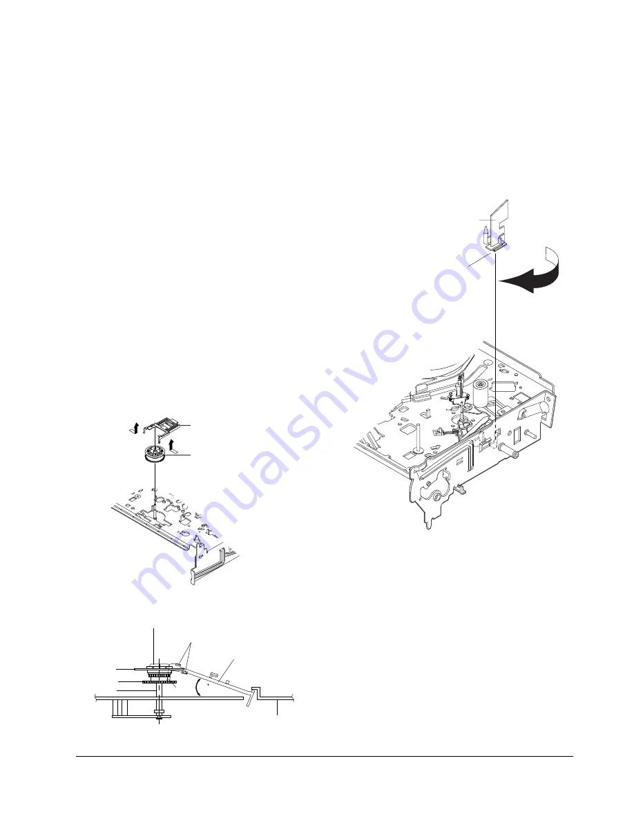
GUIDE CASSETTE DOOR
HOOK [A]
Fig. 5-31 Guide Cassette Door Removal
5-4-18 Guide Cassette Door Removal
1) Lift the Hook [A].
2) Rotate the Guide Cassette Door
Œ
in the direction
of arrow.
Note
: After reinstalling the Guide Cassette Door
Œ
sure the Hook [A].
5-4-17 Lever Up Down Ass’y, Gear Center
Ass’y Removal
1) Remove the 2 hooks in the direction of arrow as
shown Fig. 5-28 and lift the Lever Up Down Ass’y
Œ
.
2) Lift the Gear Center Ass’y
´
.
Assembly
:
1) Insert the Lever Up Down Ass'y
Œ
in the rectan-
gular holes on Main Base as shown in Fig 5-30.
2) Lift the Lever Up Down Ass'y
Œ
about 35°.
(Refer to Fig 5-30)
3) Insert Ring of the Gear Center Ass'y
´
in the
Guide of the Lever Up Down Ass'y
Œ
.
4) Insert the Gear Center Ass'y
´
in the post on
Main Base.
5) Push down the Lever Up Down Ass'y
Œ
for
locking of the Hook.
Note
:
1) Take care not to separate and sentence does not
mark sense.
2) Be sure to confirm that Ring of the Gear Center
Ass'y
´
is in the Guide of the Lever Up Down
Ass'y
Œ
after finishing assembly of Lever Up
Down Ass'y
Œ
and Gear Center Ass'y
´
.
Œ
LEVER UP DOWN ASS`Y
´
GEAR CENTER ASS`Y
MAIN BASE
LEVER UP DOWN ASS'Y
GUIDE
GEAR CENTER ASS'Y
RING
GEAR
POST
HOOK
35
Fig. 5-29 Lever Up Down Ass’y Removal
Fig. 5-30 Lever Up Down Ass’y Removal
Содержание SV-DVD40
Страница 82: ...Circuit Operating Descriptions 7 7 Fig 7 12 Block Diagram ...
Страница 116: ...Circuit Operating Descriptions 7 41 3 Block Diagram Fig 7 38 LA70100M Block Diagram ...
Страница 141: ...VCR Deck Operating Description 8 12 Samsung Electronics Fig 8 14 Mecha Timing Chart ...
Страница 156: ...Samsung Electronics 11 1 11 Wiring Diagram ...
Страница 158: ...Schematic Diagrams 12 2 Samsung Electronics 6 1 S M P S ...
Страница 159: ...Schematic Diagrams Samsung Electronics 12 3 6 2 Power Drive ...
Страница 160: ...Schematic Diagrams 12 4 Samsung Electronics DT701 6 3 Display Function ...
Страница 161: ...Schematic Diagrams Samsung Electronics 12 5 6 4 System Control Servo ...
Страница 162: ...Schematic Diagrams 12 6 Samsung Electronics 6 5 A V ...
Страница 163: ...Schematic Diagrams Samsung Electronics 12 7 6 6 Hi Fi ...
Страница 164: ...Schematic Diagrams 12 8 Samsung Electronics 6 7 A2 NICAM ...
Страница 165: ...Schematic Diagrams Samsung Electronics 12 9 6 8 SECAM Option ...
Страница 166: ...Schematic Diagrams 12 10 Samsung Electronics 6 9 OSD VPS PDC ...
Страница 167: ...Schematic Diagrams Samsung Electronics 12 11 6 10 TM ...
Страница 168: ...Schematic Diagrams 12 12 Samsung Electronics 6 11 Input Output ...
Страница 169: ...Schematic Diagrams Samsung Electronics 12 13 6 12 DVD AV Decoder ...
Страница 170: ...Schematic Diagrams 12 14 Samsung Electronics 6 13 DVD Servo ...
Страница 171: ...Schematic Diagrams Samsung Electronics 12 15 6 14 DVD Audio Video ...


