VCR Deck Operating Description
8-18
Samsung Electronics
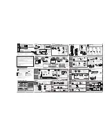
Fig. 8-24 Tape Loading Operation (Position II)
T slider assembly
No. 9 guide lever
T brake (soft)
S brake (off)
Tension lever
S slider assembly
<Tape loading>
(1) After slot-in operation (cassette loading), FL cam gear rotates and the cam slider starts shifting, and a loading
gear is ready to start.
Under this condition, the mechanism status is as follows :
1) The T main brake actuates so that tape does not com out from the T reel during the loading operation.
(2) The cylinder starts to rotates after the loading motor is rotated.
(3) When the cam slider reaches the position II (loading/unloading modes), the mechanism enters the loading
status and operates as described below.
1) S,T sliders are moved through the loading drive gear and trun on the tension post.
2) The No. 9 guide is loaded.
3) The pinch roller is loaded up to front of the capstan.
4) The head cleaner is actuated during loading operation.
5) The S soft brake is actuated.
(4) When the cam slider passes through the position III, and detects the position IV (playback standby mode),
the loading motor stops. Under this condition, the mechanism status is described as below :
Œ
The pinch roller is pressed to the capstan.
´
The No.9 guide is stored in the cassette.
ˇ
The tension post touches the tape, band brake force is applied, and the tension servo brake mechanism
actuates.
¨
Brakes for the reel discs are all off.
Содержание SV-DVD40
Страница 82: ...Circuit Operating Descriptions 7 7 Fig 7 12 Block Diagram ...
Страница 116: ...Circuit Operating Descriptions 7 41 3 Block Diagram Fig 7 38 LA70100M Block Diagram ...
Страница 141: ...VCR Deck Operating Description 8 12 Samsung Electronics Fig 8 14 Mecha Timing Chart ...
Страница 156: ...Samsung Electronics 11 1 11 Wiring Diagram ...
Страница 158: ...Schematic Diagrams 12 2 Samsung Electronics 6 1 S M P S ...
Страница 159: ...Schematic Diagrams Samsung Electronics 12 3 6 2 Power Drive ...
Страница 160: ...Schematic Diagrams 12 4 Samsung Electronics DT701 6 3 Display Function ...
Страница 161: ...Schematic Diagrams Samsung Electronics 12 5 6 4 System Control Servo ...
Страница 162: ...Schematic Diagrams 12 6 Samsung Electronics 6 5 A V ...
Страница 163: ...Schematic Diagrams Samsung Electronics 12 7 6 6 Hi Fi ...
Страница 164: ...Schematic Diagrams 12 8 Samsung Electronics 6 7 A2 NICAM ...
Страница 165: ...Schematic Diagrams Samsung Electronics 12 9 6 8 SECAM Option ...
Страница 166: ...Schematic Diagrams 12 10 Samsung Electronics 6 9 OSD VPS PDC ...
Страница 167: ...Schematic Diagrams Samsung Electronics 12 11 6 10 TM ...
Страница 168: ...Schematic Diagrams 12 12 Samsung Electronics 6 11 Input Output ...
Страница 169: ...Schematic Diagrams Samsung Electronics 12 13 6 12 DVD AV Decoder ...
Страница 170: ...Schematic Diagrams 12 14 Samsung Electronics 6 13 DVD Servo ...
Страница 171: ...Schematic Diagrams Samsung Electronics 12 15 6 14 DVD Audio Video ...


