background image

1

INFORMATION

No.

INF01/48

Date:

February 2002

Product:

SM2000 Videographic Recorder

Manual:

IM/SM2000

SM2000

SmartMedia Hardware Installation

n

o

i

t

p

i

r

c

s

e

D

.

o

N

t

r

a

P

y

t

Q

y

l

b

m

e

s

s

A

-

b

u

S

a

i

d

e

M

t

r

a

m

S

1

6

0

0

/

0

0

0

2

R

G

1

w

e

r

c

S

0

1

x

5

.

2

M

3

2

8

1

1

B

2

k

n

i

L

B

C

P

0

5

2

9

B

2

7

4

µ

r

o

t

i

c

a

p

a

C

m

u

l

a

t

n

a

T

V

6

1

F

1

5

6

6

B

1

0

0

0

2

M

S

t

e

e

h

S

n

o

i

t

a

m

r

o

f

n

I

n

o

i

t

a

ll

a

t

s

n

I

e

r

a

w

d

r

a

H

a

i

d

e

M

t

r

a

m

S

8

4

/

1

0

F

N

I

1

d

n

a

g

n

il

d

n

a

H

a

i

d

e

M

t

r

a

m

S

l

a

u

n

a

M

e

r

a

C

M

S

-

0

0

0

1

M

S

/

M

I

1

Note.

When installing SmartMedia hardware, the

Main Board in instruments manufactured prior to January,
2002 must be modified by fitting a 47µF capacitor. This
work must be carried out by a Company Approved Service
Engineer to avoid invalidating the instrument's warranty.

2

Tools Required

Medium, flat-bladed screwdriver

No. 1 Pozidriv screwdriver

Fine-tipped soldering iron

1

Introduction

This information sheet describes the procedure for fitting
SmartMedia hardware to SM2000 instruments.

Note.

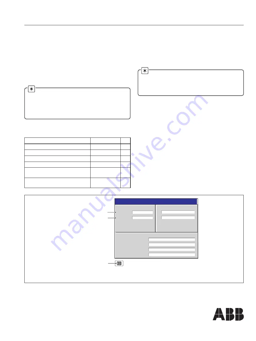
The SmartMedia upgrade requires 2002

issue 8.0 or later Application Code and 1002 issue 6.0 or
later System Code to function correctly – see Fig. 1.1 for
details of checking the Code versions. This information
sheet also details the procedure for downloading and
installing the Application and System Code.

The 

SmartMedia Service Pack

, GR2000/0702, includes the

following items:

Instrument Status

28/01/02

Group 1 filename

Process Group 1 – OFF

Group 2 filename

% Memory used

Time left

Process Group 2 – OFF

80.5%

5 days

ARCHIVING

A

Not Used

B

Not Used

CJ TEMPERATURES

VERSION

Software

2002/8

System

1002/6

Application Code Version

System Code Version

Use the Group key to

select the Status View

Fig. 1.1 Checking the Instrument Operating Software Versions

Summary of Contents for SmartMedia SM2000

Page 1: ...alidating the instrument s warranty 2 Tools Required Medium flat bladed screwdriver No 1 Pozidriv screwdriver Fine tipped soldering iron 1 Introduction This information sheet describes the procedure f...

Page 2: ...ng screw 1 2 3 Information Refitting is the reverse of removal Fig 3 1 Removing the Instrument from its Case 3 Remove the chassis top cover and PCB locking bar see Fig 3 2 3 Fitting Media Board Sub As...

Page 3: ...w the main board from the chassis 3 Disconnect the touchscreen connector from the main board 2 Slot D 1 Connection locking bar Note To disconnect the display flexi circuit it may be necessary to remov...

Page 4: ...out by a Company Approved Service Engineer 3 Fitting Media Board Sub Assembly Figs 3 1 to 3 7 5 Refer to Fig 3 4 and check the part number of the Main Board ve leg below C14 Reverse of Main Board Show...

Page 5: ...is already fitted to the instrument Fig 3 5 Removing the Media Board Sub Assembly Information Refitting is the reverse of removal 1 Check that PCB link LK1 is fitted and ensure it is in the correct po...

Page 6: ...5 Caution When positioning the chassis top cover take care not to damage the EMC contacts Fig 3 7 Refitting the PCB Locking Bar and Chassis Top Cover 3 Fitting Media Board Sub Assembly Figs 3 1 to 3 7...

Page 7: ...e instrument Operating System requires upgrading to 2002 issue 8 0 or later Application Code and 1002 issue 6 0 or later System Code see Fig 1 1 for details of checking the Code versions 1 Isolate the...

Page 8: ...Internal File View button 3 Insert a memory card containing a folder named SM2000 2 4 Downloading and Installing the Operating System Software Figs 4 1 to 4 5 4 Refit the instrument to the case see Fi...

Page 9: ...ect the PC Configurator Cable Part No C100 0051 to the RS232 Serial Port of the PC 3 Fig 4 3 Connecting the PC Configurator Cable 4 Downloading and Installing the Operating System Software Figs 4 1 to...

Page 10: ...rt Recorders Fig 4 5 Creating the Binary Partition 11 Restore the power supply to the instrument and start the download of the new software by clicking on the Program button on the SM2000 Serial Downl...

Page 11: ...fit the instrument to the case see Fig 4 1 18 Restore the power supply to the instrument 19 Follow the on screen instructions and perform touchscreen calibration Caution Do not use sharp objects such...

Page 12: ...ntained herein without notice Printed in UK 02 02 ABB 2002 ABB Ltd Howard Road St Neots Cambridgeshire PE19 8EU UK Tel 44 0 1480 475 321 Fax 44 0 1480 217 948 ABB Inc 125 E County Line Road Warminster...

Reviews: