


ENGLISH
17
9.2.1.1
OIL CHANGE INTERVALS
Normal oil change intervals are 4 000 operating hours or not more than
6 months. For pumps on hot service or in severely damp or corrosive
atmosphere, the oil will require changing more frequently. Lubricant
and bearing temperature analysis can be useful in optimizing lubricant
change intervals. The lubricating oil should be a high quality mineral oil
having foam inhibitors. Synthetic oils may also be used if checks show
that the rubber oil seals will not be adversely affected.
The bearing temperature may be allowed to rise to 50 ºC above
ambient, but should not exceed 82 ºC (API 610 limit).
A continuously rising temperature, or an abrupt rise, indicates a
fault.
9.2.1.2
GREASE CHANGE INTERV ALS
When grease nipples are fitted, one charge between grease changes is
advisable for most operating conditions; ie 2 000 hours interval. Normal
intervals between grease changes are 4 000 hours or not more than 6
months. The characteristics of the installation and severity of service will
determine the frequency of lubrication. Lubricant and bearing
temperature analysis can be useful in optimizing lubricant change
intervals. The bearing temperature may be allowed to rise to 55 ºC
above ambient, but should not exceed 95 ºC. For most operating
conditions, a quality grease having a lithium soap base and NLGI
consistency of No 2 or No 3 is recommended. The drop point should
exceed 175 ºC.
NEVER MIX GREASES CO NTAINING DIFFERENT B ASES,
THICKENERS OR ADDITI VES.
9.2.1.3
USE OF OIL LUBRICATE D BEARING BRACKETS
Oil lubricated bearing brackets should be filled with oil to the correct
level :
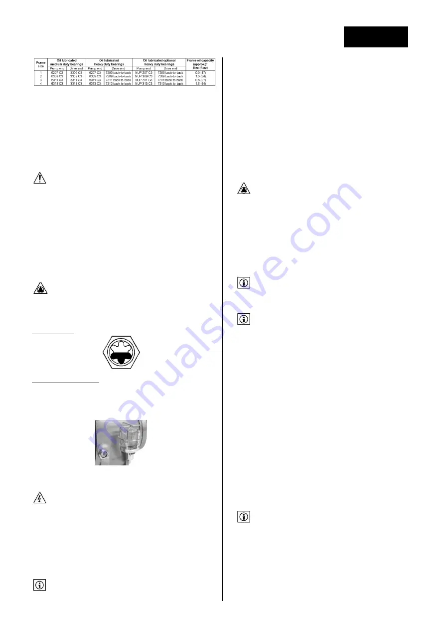
Oil level indicator :
Use of a constant level oiler :
Unscrew and rotate the bottle.
Fill the tank with oil.
Put it back in its vertical position.
Repeat filling of the bottle until oil remains visible in the bottle.
9.3
DISMANTLING AND RE-ASSEMBLY
9.3.1
DISMANTLING
Make sure that electric power is disconnected and could not be
switched on again by fault during maintenance operations.
• Drain the piping at least between the isolating valve on suction and
discharge sides.
• If necessary disconnect any measuring sensors and gauges.
• Remove drain plug and drain the pump casing.
• If necessary, remove connections to mechanical seal auxiliary piping.
• If necessary drain oil from bearing bracket and remove constant level
oiler to avoid damages during following operations.
• Pump casing can be kept fastened to pipe work.
• Remove motor fastening screws and move the motor rearward so that
there is enough space to remove the back pull-out assembly.
When using a coupling with spacer part, it is not necessary to
move the motor rearward.
9.3.1.1 DISMANTLING T HE BEARING BRACKET
1. Disconnect all auxiliary pipes where applicable.
2. Remove coupling guard and disconnect coupling.
3. If oil lubricated frame, drain oil by removing drain plug.
4. Record the gap between the bearing carrier 3240 and bearing housing
3200 so that this setting can be used during workshop assembly.
5. Place hoist sling through bearing housing adaptor window.
6. Remove casing nuts 6582.1 and support foot 3134 to baseplate
screws.
7. Remove bearing housing assembly from pump casing 1100.
8. The two threaded holes in the adaptor flange can be used for jacking
screws to assist with removal.
9. Remove pump casing seal 4590.1. A replacement gasket will be
required for assembly.
10. Clean gasket mating surfaces.
9.3.1.2 DISMANTLING T HE IMPE LLER
Never apply heat to remove the impeller. Trapped oil or lubricant
may cause an explosion.
1. Fit a chain wrench or bolt a bar to the holes in the coupling half, or fit
a keyed shaft wrench directly to the shaft.
2. Turn the shaft 2100 counter-clockwise as viewed from the drive end
of the shaft with the wrench.
3. Give the shaft a quick turn clockwise to sharply strike the wrench
handle against the work bench surface or a wooden block. A few sharp
strikes by the handle onto the bench/wooden block will free the
impeller from the shaft.
Alternatively, twist the impeller by firmly grabbing hold of the impeller
and twist it counter-clockwise to make the wrench bump on the work
bench.
This method requires the use of metal mesh reinforced gloves.
4. Remove the impeller O-ring 4610.1. Use a new O-ring for assembly.
9.3.1.3 DISMANTLING T HE MECHA NICAL SEAL
The seal manufacturer's instructions should be followed for
dismantling and assembly, but the following guidance should
assist with most seal types:
1. Remove the screws from the mechanical seal cover.
2. Remove the seal gland nuts, if a separate seal gland is fitted, and slide
the seal gland away.
3. Loosen the grub screws (used in most mechanical seals).
d) Carefully pull out the cover and mechanical seal rotating element(s).
4. Remove the seal cover 1220.
5. Remove shaft sleeve (if fitted).
6. On non-cartridge seals the stationary seat remains in the
cover/mechanical seal gland with its sealing member. Remove only if
damaged or worn out.
7. On pumps fitted with gland packing, the packing and lantern ring
should be removed only if the packing is to be replaced.
9.3.1.4 FULL DISMANTLING OF THE BEARING BRACKET
1. Take grub screw(s) out of the pump half coupling and pull out this
coupling. Remove the coupling key.
2. Remove support foot 3134 (if necessary).
3. Remove the pump side liquid deflector 2540 and/or labyrinth seal
rotary half (depending on the option fitted).
4. Slacken the bearing carrier screws to initiate bearing carrier release.
5. Remove bearing carrier 3240 and shaft 2100 assembly from the
bearing housing 3200 by pulling it towards the coupling end.
6. Remove bearing circlip 6544 (or bearing lock nut 3712.2 if paired
angular contact bearings are fitted).
Bearing carrier locking rings are left-hand thread.
7. Remove drive side v-ring 4305 and/or labyrinth seal rotary half
(depending on option fitted).
8. Remove bearing carrier 3240.
9. Remove pump side bearing 3011.
10. Release the self-locking drive side bearing nut 3712.1 and remove
drive side bearing 3013.
11. When pressing bearings off the shaft, use force on the inner race
only.
Содержание NEX
Страница 2: ......
Страница 27: ...FRAN AIS 27 12 1 1 PLAN EN COUPE Roue ouverte Roue aubes invers es...
Страница 29: ...FRAN AIS 29 13 DECLARATION CE...
Страница 30: ...FRAN AIS 30...
Страница 53: ...ENGLISH 25 12 1 1 SECTIONAL DRAWING Open impeller Reverse vane impeller...
Страница 55: ...ENGLISH 27 13 EC DECLARATION OF CONFORMITY...
Страница 56: ...ENGLISH 28...
Страница 59: ...5 1 1 1 2 2 1 2 2 SALMSON 2 3 2 4 2 4 1 25 68 5 C 2 4 2...
Страница 60: ...6 2 5 2 6 Salmson 2 7 2 8 2 9 ATEX...
Страница 62: ...8 2 9 7 2 9 8 2 9 9 3 3 1 3 2 3 3...
Страница 63: ...9 6 Salmson 3 4 25 3 4 1 4 NEX 5 5 1 NEX...
Страница 69: ...15 0 4 7 1 2 1 2 3 1 2 3 4 5 6 7 8 7 1 3 7 1 4 0 2 1...
Страница 70: ...16 Parallel Angular 7 2 7 2 1 7 2 2 L 2 3 7 2 3...
Страница 71: ...17 8 10 2 NPSHR NPSHA 7 2 4 3 3 10 0 35 2 0 7 7 3 230 400 400 400 690 690 60079 14...
Страница 72: ...18 7 3 1 Y 230 400 400 690 7 3 2 U 7 3 3 U 3 7 3 4 7 4 850 dU dt 2500 ATEX NPSHR NPSHA...
Страница 73: ...19 40 55 8 8 1 2 1 8 2 8 3 1 2 3 4 20 30 5 8 4 HMT P 100 SG 9 806 SG 7 1 4...
Страница 74: ...20 125 P 0 5 P P 0 5 0 1 0 2 3 4 4 140 20 40 8 5 Salmson 9 9 1 9 2...
Страница 86: ...32 11 12 12 1 12 1 1...
Страница 89: ...35 13...


