


ENGLISH
14
Non-return valve :
A check valve can be installed on discharge side to protect the pump
from back flow effects such as pressure surges or back flow when the
pump is stopped.
Auxiliary pipings:
For most of applications a single mechanical seal is used. If the sealing
must be equipped with auxiliary equipments check that there are no
leakages and that direction of flow is respected.
Shaft sealings :
Gland packing :
If the pump is installed for suction lift operation and the discharge
pressure is small (less than 10mwc), it will be necessary to add a quench
to avoid air intake trough the packing rings.
Single mechanical seal with external quench :
External piping system or raised tank should be installed in the state of
the art. Pressure in the quench should not exceed 0,35 bar.
Back to back mechanical seals :
When using this type of mechanical seal arrangement the use of a
barrier fluid is mandatory. Compatibility between barrier fluid and
pumped media should be confirmed.
If back to back pressurized mechanical seals are used : pressure in the
auxiliary system will be set at 2 bar minimum above the pressure
calculated in mechanical seal chamber. Check that this pressure will not
exceed max allowable pressure of MS on atmosphere side.
When high temperature fluid is pumped, the barrier fluid should
circulate even when pump is off.
If back to back non pressurized mechanical seals are used : tank filled
with the barrier fluid will be placed at a minimum height of 0,7 m above
mechanical seal level.
Tandem mechanical seals :
Compatibility between barrier fluid and pumped media should be
confirmed.
After pipe work is done turn pump shaft by hand and check it turns
freely. If it appears that it is difficult to turn pump shaft, then check
forces applied by piping to pump casing. Positioning of piping should be
done again.
7.3
ELECTRICAL CONNECTION / EARTHING
Check that motor winding corresponds to site electric power
supply characteristics before electrical connections are performed.
Connecting a 230/400V motor on a 400V power supply or
connection of a 400/690V motor on a 690V power supply might
drive to motor destruction if terminal strip are positioned in a wrong
way.
Electrical connection should be performed by qualified personnel
only having necessary agreements and in compliance with local,
national and international regulations.
Equipments used in an ATEX zone will be connected in compliance
with CEI60079-14. It is the responsibility of the end user to select
proper type and size of electric cable.
Respect motor manufacturer instructions to make electric motor
connection (refer to the instructions supplied with the motor. they
are usually indicated inside motor junction box). Sensors will be
connected in compliance with the instructions given in dedicated
instruction manual.
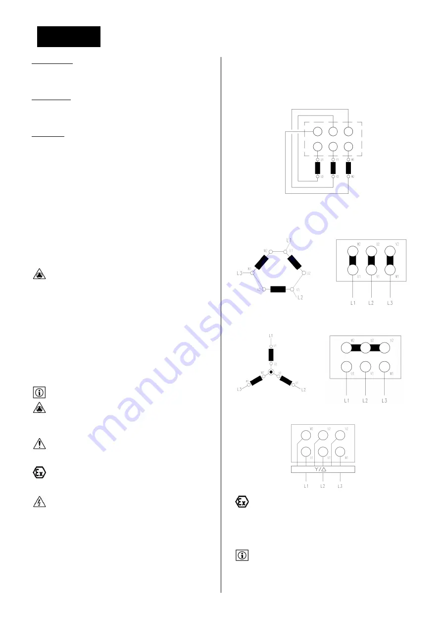
7.3.1
TERMINAL STRIP POSITIONNING FOR STAR
(Y) AND DELTA (
) CONNECTION (MULTI -
VOLTAGES ELECTRIC MO TORS)
Multi-voltage winding for voltages 230/400V and 400/690V :
6 wiring terminals :
To change motor direction of rotation reverse two phases on wiring
terminals. Connection of earthing terminal is mandatory.
7.3.2
LOWER VOLTAGE :
CONNECTION
Voltage : U
7.3.3
HIGHER VOLTAGE : Y CONNECTION
Voltage : U
3
7.3.4
Y /
STARTER :
Grounding of the complete pumpset will be performed with
special care. Earthing will avoid any electrostatic accumulation in
components of the pumpset. Each part of the pumpset should be
connected to earth with a correctly calibrated bonding strap or cable
(motor winding, motor frame, coupling guard, pump baseframe).
7.4
USE OF A FREQUENCY INVERTER
When pump is used with a variable speed drive, make sure that
the frequency inverter instructions and operating manual is
available and known.
The electric motor that is supplied with the pump may be connected
under conditions to a VSD. Variable speed will be used to reach pump
Содержание NEX
Страница 2: ......
Страница 27: ...FRAN AIS 27 12 1 1 PLAN EN COUPE Roue ouverte Roue aubes invers es...
Страница 29: ...FRAN AIS 29 13 DECLARATION CE...
Страница 30: ...FRAN AIS 30...
Страница 53: ...ENGLISH 25 12 1 1 SECTIONAL DRAWING Open impeller Reverse vane impeller...
Страница 55: ...ENGLISH 27 13 EC DECLARATION OF CONFORMITY...
Страница 56: ...ENGLISH 28...
Страница 59: ...5 1 1 1 2 2 1 2 2 SALMSON 2 3 2 4 2 4 1 25 68 5 C 2 4 2...
Страница 60: ...6 2 5 2 6 Salmson 2 7 2 8 2 9 ATEX...
Страница 62: ...8 2 9 7 2 9 8 2 9 9 3 3 1 3 2 3 3...
Страница 63: ...9 6 Salmson 3 4 25 3 4 1 4 NEX 5 5 1 NEX...
Страница 69: ...15 0 4 7 1 2 1 2 3 1 2 3 4 5 6 7 8 7 1 3 7 1 4 0 2 1...
Страница 70: ...16 Parallel Angular 7 2 7 2 1 7 2 2 L 2 3 7 2 3...
Страница 71: ...17 8 10 2 NPSHR NPSHA 7 2 4 3 3 10 0 35 2 0 7 7 3 230 400 400 400 690 690 60079 14...
Страница 72: ...18 7 3 1 Y 230 400 400 690 7 3 2 U 7 3 3 U 3 7 3 4 7 4 850 dU dt 2500 ATEX NPSHR NPSHA...
Страница 73: ...19 40 55 8 8 1 2 1 8 2 8 3 1 2 3 4 20 30 5 8 4 HMT P 100 SG 9 806 SG 7 1 4...
Страница 74: ...20 125 P 0 5 P P 0 5 0 1 0 2 3 4 4 140 20 40 8 5 Salmson 9 9 1 9 2...
Страница 86: ...32 11 12 12 1 12 1 1...
Страница 89: ...35 13...


