49
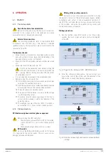
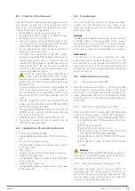
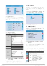
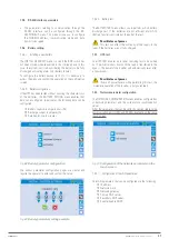
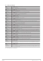
7.4.1. Device Information.
The information that the control panels can display on the
device is shown below.
Fig. 76.
Device information.
Submenu
Displayed data
SERIAL NUMBER
Serial number of the device provided by the
manufacturer and by an OEM distributor, if any.
TYPE OF DEVICE
Type of device (ON-LINE, ECO, etc.).
OPERATING MODE
This can be SINGLE or PARALLEL if the system is
in parallel with other UPSs.
OPERATING HOURS
Device operating hours (record).
CLOCK
Current system date and time setting.
Tabla 19.
Description of the information displayed.
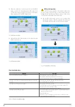
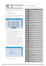
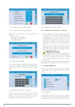
7.4.2. Parallel operation information.
The menu that contains the parallel operation information is
only active if the UPS belongs to a parallel system or load-sync
system.
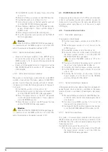
Fig. 77.
Parallel operation information.
•
In the PARALLEL INDEX section, the first number identifies
the position of the UPS in question in the parallel system.
The second number indicates the total number of units in
the system.
•
The second section, PRIORITY, can have two values:
‘MASTER’ or ‘SLAVE.’ There can only be one MASTER UPS.
•
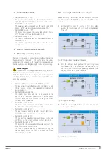
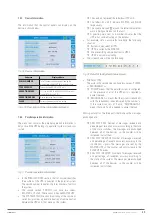
The SYSTEM STATUS section (monitoring of the communi-
cation bus) provides a general indication of communication
between the UPS units that make up the system.
The numbers represent the individual UPS units.
The letters M and S indicate MASTER and SLAVE
respectively.
The square brackets
[ ]
around the letter indicate that
work is being carried out on that unit.
A question mark next to a number indicates that the
UPS is not communicating on the data bus.
•
For example, let us assume that we have the following
situation:
System composed of 4 UPSs.
UPS2 is currently the MASTER.
We are verifying communications in UPS3.
UPS4 is not communicating.
•
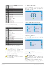
The screen shown will be the following:
Fig. 78.
Detail of the System Status screen.
•
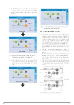
PARALLEL TYPE
The word in the second line can have two values, ‘POWER’
or ‘REDx.’
‘POWER’ means that the parallel system is configured,
so the presence of all of the UPS units is required to
power the load.
‘REDx’ means that the system is redundant,
with the redundancy index indicated by the number ‘x.’
If the system consists of 3 units, ‘RED2’
means that only 1 unit is needed to power the load.
Message statistics.
The three parts that make up the messages
exchanged are:
CAN STAT SSW: Number of messages received and
percentage of reception accuracy according to the state
of the static switches. The messages are exchanged
between all of the devices, so the counter will be
increased in all of them.
CAN STAT INV MSG0: Number of messages received
and percentage of reception accuracy according to the
synchronism signals. The messages are sent by the
MASTER UPS, so the counter will only increase in the
SLAVE UPS devices.
CAN STAT INVERTER: Number of messages received
and percentage of reception accuracy according to
the state of the system. The messages are exchanged
between all of the devices, so the counter will be
increased in all of them.
X-PERT
UNINTERRUPTIBLE POWER SUPPLIES (UPS)
USER MANUAL
Содержание SLC X-PERT Series
Страница 1: ...SLC X PERT 80 400 kVA UNINTERRUPTIBLE POWER SUPPLIES UPS USER MANUAL...
Страница 8: ...8 SALICRU Fig 3 Front view of the 400 kVA model...
Страница 18: ...18 SALICRU 880 1978 947 Air outlet openings Front air inlet openings Fig 16 Dimensions of 200 300 kVA devices...
Страница 34: ...34 SALICRU Fig 42 Connection of three UPSs through the CAN bus for 400 kVA devices...
Страница 60: ...60 SALICRU...
Страница 61: ...61 X PERT UNINTERRUPTIBLE POWER SUPPLIES UPS USER MANUAL...

