27
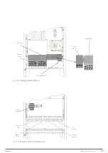
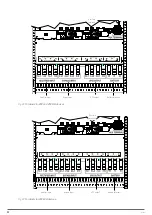
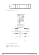
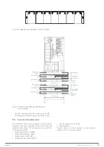
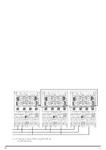
Fig. 28.
Top view of a row of batteries (12 V, 7-9-11 Ah).
Tray 6
Battery fuse nega-
tive
Tray 1
Tray 2
Tray 3
Tray 4
Tray 5
Battery fuse nega-
tive
Battery fuse negative
Battery neutral
Battery neutral
Battery neutral
Battery neutral
Battery fuse
positive
Battery neutral
Battery fuse
positive
Battery neutral
Battery fuse
positive
-B
-B
N
-B
N
N
+B
+B
N
+B
N
N
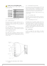
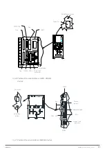
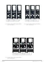
Fig. 29.
Front view of the battery connection tray
(12 V, 7-9-11 Ah).
After connection, slide the trays back into the UPS.
Replace and fix the left/right cover with the screws
supplied.
X-PERT
UNINTERRUPTIBLE POWER SUPPLIES (UPS)
USER MANUAL
Содержание SLC X-PERT Series
Страница 1: ...SLC X PERT 80 400 kVA UNINTERRUPTIBLE POWER SUPPLIES UPS USER MANUAL...
Страница 8: ...8 SALICRU Fig 3 Front view of the 400 kVA model...
Страница 18: ...18 SALICRU 880 1978 947 Air outlet openings Front air inlet openings Fig 16 Dimensions of 200 300 kVA devices...
Страница 34: ...34 SALICRU Fig 42 Connection of three UPSs through the CAN bus for 400 kVA devices...
Страница 60: ...60 SALICRU...
Страница 61: ...61 X PERT UNINTERRUPTIBLE POWER SUPPLIES UPS USER MANUAL...


