2
SALICRU
General index
1. INTRODUCTION.
1.1. THANK YOU LETTER.
2. SAFETY INFORMATION.
2.1. USING THIS MANUAL.
2.1.1. Conventions and symbols used.
3. QUALITY ASSURANCE AND STANDARDS.
3.1. STATEMENT BY THE MANAGEMENT.
3.2. STANDARDS.
3.2.1. First and second environment.
3.2.2. First environment.
3.2.3. Second environment.
3.3. ENVIRONMENT.
4. PRESENTATION.
4.1. VIEWS.
4.1.1. Views of the device.
4.2. DEFINITION OF THE PRODUCT.
4.2.1. Nomenclature.
4.3. UPS NAMEPLATE.
4.4. DESCRIPTION OF THE UPS.
4.5. OPERATING PRINCIPLE.
4.5.1. Rectifier.
4.5.2. Inverter.
4.5.3. Batteries and battery charger.
4.5.4. Static bypass.
4.5.5. Manual bypass.
4.6. OPERATING STATES.
4.6.1. Normal operation.
4.6.2. High-Efficiency.
4.6.3. Bypass operation.
4.6.4. Battery operation.
4.6.5. Manual bypass.
4.7. OPERATION AND CONTROL DEVICES.
4.7.1. Circuit breakers.
4.7.2. Emergency power off button (EPO).
4.7.3. Normal/Bypass selector.
4.7.4. Control panel with LCD.
4.8. OPTIONAL EXTRAS.
4.8.1. Isolation transformer.
4.8.2. External manual maintenance bypass.
4.8.3. Communication card.
4.8.3.1. Integration into computer networks using an SNMP adapter.
4.8.3.2. RS-485 MODBUS.
4.8.3.3. Relay interface.
5. INSTALLATION.
5.1. RECEPTION OF THE DEVICE.
5.1.1. Reception, unpacking and contents.
5.1.2. Storage.
5.1.3. Unpacking.
5.1.4. Transport to the site.
5.1.5. Siting.
5.1.5.1. Siting for single devices.
5.1.5.2. Siting for parallel systems.
5.1.6. Plan view of the base, static load and weights.
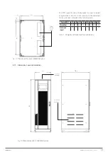
5.1.7. Dimensions, space and ventilation.
5.1.8. Environmental conditions of the installation.
5.2. CONNECTIONS.
5.2.1. Connection to the mains.
5.2.2. Battery connection.
5.2.3. Connection of the auxiliary cables.
5.2.3.1. External manual bypass.
5.2.3.2. Normal/Bypass selector.
5.2.3.3. External output switch.
5.2.3.4. Remote emergency power off button.
5.2.3.5. Auxiliary batteries contact.
5.2.3.6. Auxiliary diesel generator contact.
5.2.4. Serial interface.
5.2.5. Relay interface connection.
6. OPERATION.
6.1. STARTUP.
6.1.1. Pre-startup checks.
6.1.2. Startup procedure.
6.2. SHUTDOWN PROCEDURE.
6.3. MANUAL (OR MAINTENANCE) BYPASS.
6.3.1. Manual bypass transfer procedure.
6.3.2. Restarting the UPS from the manual bypass.
6.4. REDUNDANT PARALLEL SYSTEM.
6.4.1. Verification of the parallel system.
6.4.2. Operating states of the redundant parallel system.
6.4.3. System behaviour.
6.4.4. Redundant parallel system startup.
Содержание SLC X-PERT Series
Страница 1: ...SLC X PERT 80 400 kVA UNINTERRUPTIBLE POWER SUPPLIES UPS USER MANUAL...
Страница 8: ...8 SALICRU Fig 3 Front view of the 400 kVA model...
Страница 18: ...18 SALICRU 880 1978 947 Air outlet openings Front air inlet openings Fig 16 Dimensions of 200 300 kVA devices...
Страница 34: ...34 SALICRU Fig 42 Connection of three UPSs through the CAN bus for 400 kVA devices...
Страница 60: ...60 SALICRU...
Страница 61: ...61 X PERT UNINTERRUPTIBLE POWER SUPPLIES UPS USER MANUAL...


