21
•
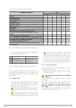
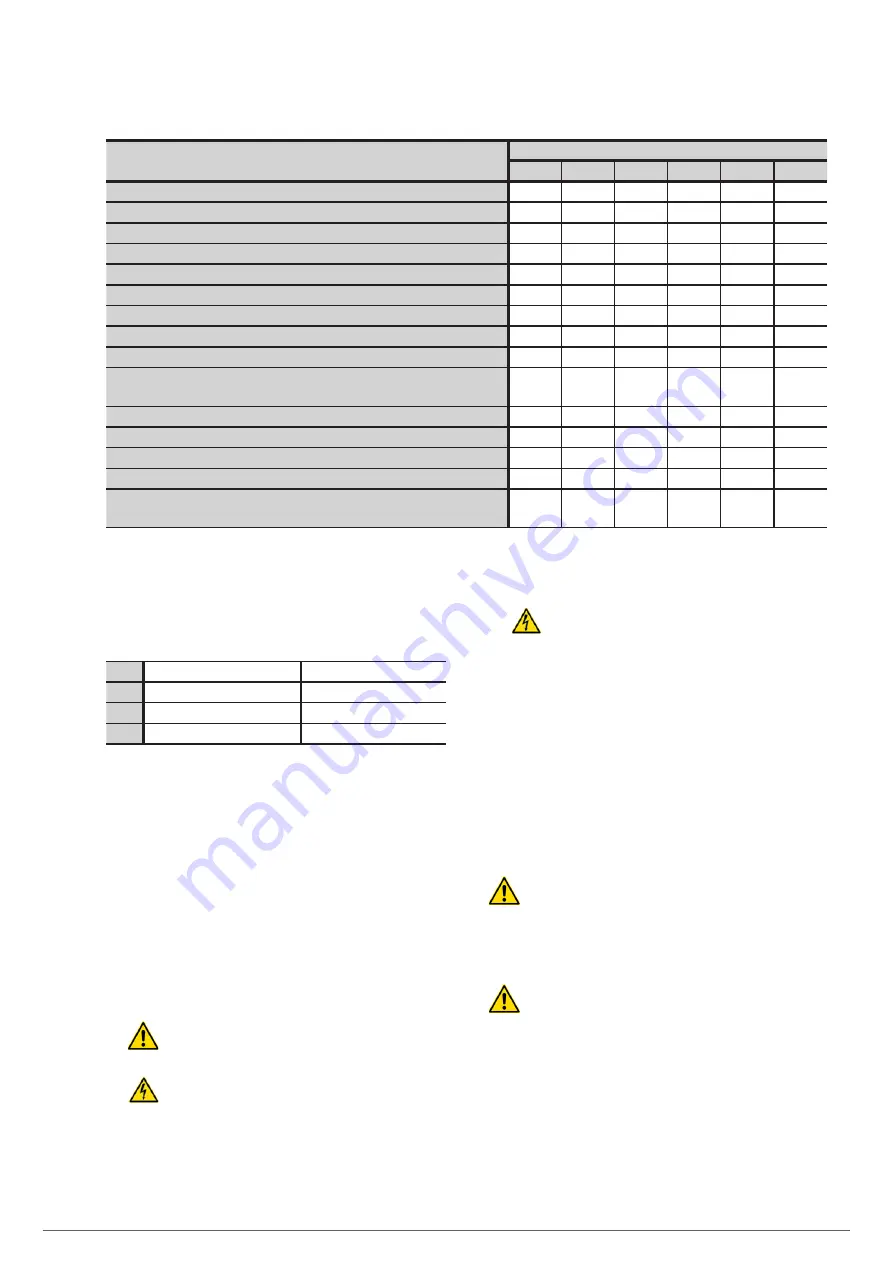
Classification of chemically active substances
(EN 60721-3-3).
ENVIRONMENTAL PARAMETER
CLASS
3C1R
3C1L
3C1
3C2
3C3
3C4
Marine salt.
No
No
No
Salt spray Salt spray Salt spray
Sulphur dioxide (mg/m
3
).
0.01
0.1
0.1
1.0
10
40
Hydrogen sulphide (mg/m
3
).
0.0015
0.01
0.01
0.5
10
70
Chlorine (mg/m
3
).
0.001
0.01
0.1
0.3
1.0
3.0
Hydrochloric acid (mg/m
3
).
0.001
0.01
0.1
0.5
5.0
5.0
Hydrofluoric acid (mg/m
3
).
0.001
0.003
0.003
0.03
2.0
2.0
Ammonia (mg/m
3
).
0.03
0.3
0.3
3.0
35
175
Ozone (mg/m
3
).
0.004
0.01
0.01
0.1
0.3
2.0
Nitrous oxide (in values equivalent to nitrogen dioxide) (mg/m
3
).
0.01
0.1
0.1
1.0
9.0
20
Places with a strictly monitored and controlled atmosphere (‘clean space’
category).
X
Places with a continuously controlled atmosphere.
X
Places in rural and urban areas with few industrial activities and moderate traffic.
X
Places in urban areas with activities and/or heavy traffic.
X
Places near factories with chemical emissions.
X
Places inside industrial facilities. Emission of highly concentrated polluting
chemical substances.
X
Tabla 9.
Classification of chemically active substances.
•
The UPS is designed to be installed in an environment that
meets the following classifications.
K
Weather conditions
According to technical data sheet
B
Biological conditions
3B1 (EN 60721-3-3)
C
Chemically active substances
3C2 (EN 60721-3-3)
S
Mechanically active substances
3S2 (EN 60721-3-3)
Tabla 10.
Characteristics of the location of the device.
If the environmental conditions of the installation location do
not meet the indicated requirements, it will be necessary to
take additional precautions to reduce values in excess of the
specified limits.
5.2. CONNECTIONS.
•
A bad connection or switching operation can cause faults
in the UPS and/or the loads connected to it. Read the
instructions in this manual carefully and follow the steps
indicated in the order established.
The devices can be installed and used by personnel
without specific training simply with the help of this
manual.
It should never be forgotten that a UPS is a generator
of electrical energy, and, as such, the user must take
all necessary precautions against direct or indirect contact.
All of the device’s connections, including those
related to control (interface, EPO, etc.), must be
made without mains power present and the UPS set to ‘Off.’
•
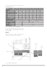
To connect a device to an optional battery module, or
between modules, or to install an optional card in the slot,
it is necessary to remove its respective protective metal
cover screwed to the UPS. Remove the screws and cover.
5.2.1. Connection to the mains.
For electrical connection of 80... 400 kVA devices to the mains,
connect the following cables:
•
AC power from the rectifier and the bypass power supply.
•
AC output of the loads.
Risk of damage to the device due to insufficient
isolation.
The cables must be protected against short-circuits and current
earth leakage.
The connection points must be hermetically sealed to prevent air
from being sucked into the ducts where the cables are housed.
Risk of damage to the device due to incorrect
wiring.
To connect the device, follow the electrical diagram carefully
and respect the polarity of the cables.
X-PERT
UNINTERRUPTIBLE POWER SUPPLIES (UPS)
USER MANUAL
Содержание SLC X-PERT Series
Страница 1: ...SLC X PERT 80 400 kVA UNINTERRUPTIBLE POWER SUPPLIES UPS USER MANUAL...
Страница 8: ...8 SALICRU Fig 3 Front view of the 400 kVA model...
Страница 18: ...18 SALICRU 880 1978 947 Air outlet openings Front air inlet openings Fig 16 Dimensions of 200 300 kVA devices...
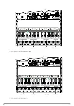
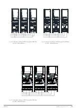
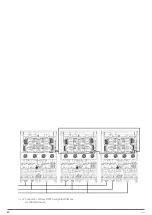
Страница 34: ...34 SALICRU Fig 42 Connection of three UPSs through the CAN bus for 400 kVA devices...
Страница 60: ...60 SALICRU...
Страница 61: ...61 X PERT UNINTERRUPTIBLE POWER SUPPLIES UPS USER MANUAL...


