


11
be increased. This operating mode is called
High-Efficiency
.
Although they charge periodically, the state that predominates
is complete standby.
4.5.4. Static bypass.
The static bypass makes it possible to switch the load or
loads between the inverter and the emergency mains and vice
versa, without cutting. As power switching elements, it uses
thyristors (SCR).
4.5.5. Manual bypass.
The manual bypass is used to isolate the UPS completely,
powering the load directly from the input mains in case of
maintenance or serious failures.
Manual bypass transfer operations and return to normal
functioning must be carried out according to the steps
established in the relevant chapter of this document. The user
will be solely responsible for any faults caused to the UPS,
loads and/or installation as a result of incorrect actions.
External manual bypass
.
In addition to the standard internal manual bypass, it is
possible to optionally install an external manual bypass.
4.6. OPERATING STATES.
The UPS has five operating modes:
•
Normal operation
•
High-Efficiency operation
•
Static bypass operation
•
Battery operation
•
Manual bypass operation
4.6.1. Normal operation.
In normal operation, all switches/circuit breakers are in the ON
position, except the MBCB (maintenance bypass).
The rectifier is powered by three-phase AC input voltage
and this in turn powers the inverter and compensates for
the variation in the mains voltage and load, thus keeping the
DC voltage constant. At the same time, it is responsible for
charging the batteries. The inverter converts the DC voltage
into a sine waveform with stabilised voltage and frequency,
and also powers the load through its static SSI switch.
Mains
Mains
Output
Fig. 6.
Normal operation.
4.6.2. High-Efficiency.
In this operating mode, the batteries are disconnected from
the DC bus by means of a static switch, and the rectifier
operates with reduced DC voltage; a control algorithm allows
the batteries to be reconnected periodically for recharging
purposes (intermittent charging).
Mains
Mains
Output
Fig. 7.
High-Efficiency operation.
When the High-Efficiency algorithm is active, the rectifier
operates with reduced DC voltage and only powers the inverter,
since the batteries are disconnected from the DC bus. Battery
charging is controlled by a specific algorithm. In the event that
no mains outage events have occurred and therefore no battery
discharges, the control logic provides a charging cycle every 25
days. The battery charger restores capacity lost from any self-
discharge and remains in float charge mode for an additional
12 hours. As this time passes, the battery switch opens and the
batteries disconnect from the DC bus.
In the event of a discharge event, the control logic calculates
the capacity that was lost during the discharge; as the mains
are restored, a load cycle is initiated and this is extended for an
additional time that depends on the percentage of lost capacity
with respect to the rated value.
•
Loss of capacity <10%
→
Additional load for 12 hours.
•
Loss of capacity between 10% and 20%
→
Additional load
for 48 hours.
•
Loss of capacity >20%
→
Additional load for 96 hours.
These values comply with the recommendations of the
major battery manufacturers.
Adjust battery capacity correctly.
The front panel of the UPS enables adjustment of the
parameters of the batteries, including the rated capacity. Taking
into account the importance of such a value for the correct
execution of the control algorithm, it is highly advisable to
verify the accuracy of the programmed value.
4.6.3. Bypass operation.
The load can be transferred to bypass both automatically and
manually. Manual transfer is carried out using the ‘Normal/
Bypass’ selector, which forces the load to be powered by the
bypass. In the event of fault or failure of the bypass line, the
load is transferred back to the inverter, all without interruption
and without altering the power to the loads.
X-PERT
UNINTERRUPTIBLE POWER SUPPLIES (UPS)
USER MANUAL
Содержание SLC X-PERT Series
Страница 1: ...SLC X PERT 80 400 kVA UNINTERRUPTIBLE POWER SUPPLIES UPS USER MANUAL...
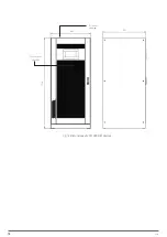
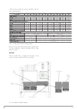
Страница 8: ...8 SALICRU Fig 3 Front view of the 400 kVA model...
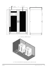
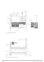
Страница 18: ...18 SALICRU 880 1978 947 Air outlet openings Front air inlet openings Fig 16 Dimensions of 200 300 kVA devices...
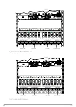
Страница 34: ...34 SALICRU Fig 42 Connection of three UPSs through the CAN bus for 400 kVA devices...
Страница 60: ...60 SALICRU...
Страница 61: ...61 X PERT UNINTERRUPTIBLE POWER SUPPLIES UPS USER MANUAL...


