26
4.3.7. "Dry_in" terminals, remote
ON-OFF (0,7 to 3 kVA equipments
only).
Ŗ
The equipments from 0,7 to 3 kVA have a 4 pins connector,
two for the EPO (see the description in the previous section)
and two for remote start up
RU
shutdown "Dry_in".
Ŗ
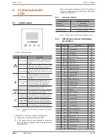
Through these terminals, an external button can be con-
nected, with the same function that the own in the UPS.
Ŗ
When pressing, over it for 1 second, the circuit will activate
the opposite order of the current status of the inverter, so, if
it is shutdown then it will be started up and vice versa, if the
inverter is started up then it will be shutdown (see figure 14).
External button, normally open.
It is activated with an order of 1
second pulsation.
1
4
+ VDC
EPO
Dry_in
Fig. 14.
Button installation in the "Dry_in" terminals.
4.3.8. "Dry_out" terminals, dry contact
for alarm (0,7 to 3 kVA equipments
only).
Ŗ
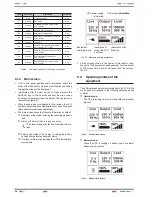
The equipments from 0,7 to 3 kVA are supplied with a nor-
mally open dry contact "Dry_out", which is closed when
activating of any on or more associated alarms "Summary
Alarm" from Table 4.
Ŗ
Do not apply more than 30V AC 1A or 60V DC 2A. Dry
contact, do not connect both phases between the
contacts, because there would be a short-circuit when trig-
gering the alarm because the circuit is closed.
1
2
4
3
Dry contact, do not apply voltage
between them.
Fig. 15.
Dry contact "Dry_out".
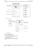
BUS Over Voltage
Inv Under Voltage
BUS Under Voltage
Inv Softstart Fail
BUS Unbalance
Output Overload
BUS Short
Inv Overload Fault
BUS Softstart Fail
Byp Overload Fault
Output Short Circuit
Heatsink Over temperature
Inv Over Voltage
-
Table 4.
Associated alarms to "Summary alarm" for Dry_out contact.
4.3.9. Connection in parallel.
4.3.9.1. Introduction to the redundancy.
N+1 is usually the most reliable power structure. N means the min-
imum quantity of equipments that the total load needs, so 1, and
1 means the quantity of redundant equipments, so it means, the
quantity of faulty UPSs that the system can allow at the same time.
TWIN RT
series allows two equipment connected in parallel
only, for those models with power rate between 4 and 10 kVA, in
order to set a shared output and redundant in power.
4.3.9.2. Installation and parallel operating (4 to 10
kVA equipments only).
Ŗ
Communication line (COM) is a very low voltage circuit
of safety. To preserve the quality, it has to be installed
separate from other lines that have dangerous voltages (energy
distribution line).
Ŗ
Parallel connection bus
. Use the bundle with 25 signal
cables with mesh and DB25 connectors in the ends to joint
up to 2 equipments as maximum. Each bundle has a male
and female connector in the ends, which will have to be con-
nected to joint both equipments. It is essential to close the
loop of the parallel bus.
The length of the parallel cable has 3 metres and it can't be
extended under any other concept due to the risk of interfer-
ences and communication failures that it could cause.
Ŗ
The installation of the parallel systems, has to be provided
by a switchgear panel with individual protections for input,
output and static bypass (this last one, in those installations
that uses the second line only), also a manual bypass with
mechanical lock, see figures 16 and 17.
This switchgear panel allows isolating only one equipment from
the system, against any failure and feed the loads with the rest
of equipments during the preventive maintenance or its fixing. In
the same way, it allows removing an equipment in parallel and
replace it or put it in parallel again once it is fixed, but without
breaking the power supply to the loads meanwhile the con-
nected power can be supported by the operative equipment.
Under request a manual bypass panel can be supplied for a
single equipment or a system of two equipments in parallel.
Ŗ
Respect the connection procedure for input and bypass de-
scribed in the previous sections of this chapter.
Ŗ
Respect the established procedure to make the connection of
the battery modules for those equipments with extended back
up time, which has been described in the previous sections of
this chapter.
Ŗ
Respect the established procedure to make the connection of
the output (loads), which has been described in the previous
sections of this chapter.
Ŗ
Respect the established procedure to make the connection
of the output and batteries of the equipment, which has been
described in the previous sections of this chapter.
Ŗ
In parallel systems, the length and cross section of the
cables that go from the switchgear panel till one of the
UPSs and vice versa, will be the same for all of them without
any exception.
In the worst case, the following deviations have to be strictly
respected:
When the distance among the UPSs and protection
panel is lower than 20 metres, the difference in the length
between the input and output cables of the equipments
has to be lower than 20%.
USER MANUAL
Содержание SLC TWIN RT series
Страница 2: ......
Страница 49: ...49 SALICRU...
Страница 50: ...50 USER MANUAL...
Страница 51: ...51 SALICRU...


