


33
SALICRU
6. Control panel with
LCD.
6.1. Control
panel.
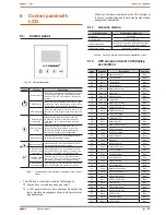
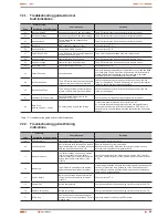
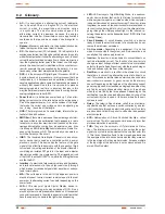
Fig. 20.
Control panel view.
Button
Function
Description
Inverter start up
With no AC power supply and battery connected
to the equipment (B0 or B1 equipments), press
the button for 3 sec. as minimum to start up the
inverter.
UPS start up
When the unit is supplied from the AC input
voltage and it is on bypass mode, press the key
for more than 3 sec. to start up the inverter.
UPS shutdown
When the equipment is ON and it has to be
shutdown, presss for more than 3 sec. over this
key.
Enter into the
main menu
When showing the main screen of the UPS
by default in the LCD, press over this key for
more than 1 sec. to enter into the main menu
structure.
Exit from main
menu
Press over this key for more than 1 sec. to
escape from the current menu, to the menu
by default in the UPS, without executing any
command or changing any configuration.
Move upwards
Press this key for 1 sec. as minimum to move
up in the browsing inside a menu.
Move downwards Press this key for 1 sec. as minimum to move
down in the browsing inside a menu.
Enter into the
structure of the
next menu
Press this key for 1 sec. as minimum to select
the option in the current menu or to enter in the
next menu, but without changing any setting.
Select an option
of the menu
Press the key for 1 sec. as minimum to select
the option in the current menu or to enter in the
next menu, but without changing any setting.
Validate the
current setting
Press the key for 1 sec. as minimum to validate
the modified option and change the settings.
Tabla 7.
Functionality of the buttons or keypad of the control
panel.
Ŗ
The UPS has a control panel with the following parts:
Four buttons or membrane keys, see table 7.
A LCD panel with two colours backlight. By default, the
text or graphics messages are shown in white colour over
blue background.
When a critical alarm is activated on the UPS, the light of
the text or graphic changes to dark orange with orange
background (see table 9)
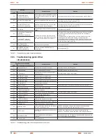
6.1.1. Acoustic
alarms.
Alarm condition
Modulation or alarm tone
Active fault
Continuous
Active warning
Beep every second
Output from battery
Beep every 4 seconds. With low battery (end
of back up time), one beep every second.
Output from bypass
Beep every 2 seconds
Tabla 8.
Acoustic alarms. Condition and modulation or tone.
6.1.2. UPS status and color LCD display,
as condition.
Code
Condition
Description
Color LCD
01
State
Bypass abnormal.
Blue
02
State
Utility abnormal.
Blue
03
State
HE abnormal.
Blue
04
Warning
Site wiring fault.
Blue
11
Warning
Battery disconnect.
Blue
12
Warning
Battery low.
Blue
13
Warning
Service battery.
Blue
15
Warning
Charger fail.
Blue
16
Warning
Battery over voltage.
Blue
17
State
ABM state charging.
Blue
18
State
ABM state floating.
Blue
19
State
ABM state resting.
Blue
1A
State
ABM state OFF.
Blue
1B
State
Battery test fail.
Blue
1C
State
Battery test interrupt.
Blue
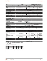
21
Fault
BUS over voltage.
Red
22
Fault
BUS under voltage.
Red
23
Fault
BUS unbalance.
Red
24
Fault
BUS short.
Red
25
Fault
BUS softstart fail.
Red
31
Fault
Output short circuit.
Red
32
Fault
Inv over voltage.
Red
33
Fault
Inv under voltage.
Red
34
Fault
Inv softstart fail
Red
41
Fault
Output overload.
Red
42
Fault
Inv overload fault.
Red
43
Fault
Bypass overload fault.
Red
51
State
UPS control power On.
Blue
52
State
UPS On from panel.
Blue
53
State
UPS On from COM.
Blue
54
State
UPS auto On
Blue
55
State
UPS Off from panel.
Blue
56
State
UPS Off from COM.
Blue
57
State
UPS auto Off
Blue
62
State
In battery mode.
Blue
63
State
In ECO mode.
Blue
Содержание SLC TWIN RT series
Страница 2: ......
Страница 49: ...49 SALICRU...
Страница 50: ...50 USER MANUAL...
Страница 51: ...51 SALICRU...