32
SALICRU
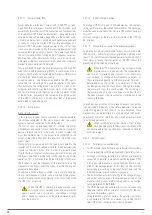
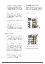
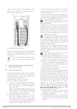
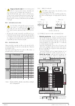
Fig. 26.
Example of a parallel system, with a single AC
network and manual bypass board.
Output circuit breaker
Manual bypass
UPS no. 1
UPS No. 'N'
Input
To loads
•••
Bypass circuit breakers
Input circuit breakers
Bypass Input
Fig. 27.
Example of a parallel system, with independent
static bypass line and manual bypass board.
•
Beyond the communication bus, it is necessary to provide
the installation with parallel systems, a board provided with
the individual input and output protections and a manual
bypass with mechanical locking. See
or
, depending on
whether or not there is an independent static bypass line.
For more information see the documentation for the "Rec-
ommended installation".
5.5.7. Interface and communications.
•
The communications line (COM) constitutes a very
low voltage safety circuit and must be installed
separately from other lines carrying dangerous voltages
(power distribution line).
5.5.7.1. Digital inputs, dry contacts and communications.
The ADAPT2 UPS series incorporates the following connec-
tions as standard for communication with external peripherals
or with other identical equipment:
•
Four digital inputs through terminal block.
•
Four relay interface outputs via terminal block.
•
Communication via RS232/RS485 ports (subD9) or USB.
•
Two slots for installing an SNMP card or relay expansion
board (IS).
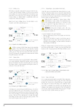
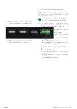
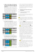
All connectors related with communications are grouped to-
gether on the interface panel and can be accessed from the
Bypass module after removing the cover, which covers them
completely.
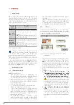
The communication interface has the following connections via
terminal block:
•
Temperature sensors input.
TBAT: Sensor for the compensation of the floating
voltage of batteries. Parameter shown on the control
panel display.
TAMB: Sensor for measuring ambient temperature. Pa-
rameter shown on the control panel display.
•
Signal input for the external EPO button.
•
4 programmable digital inputs (see
).
•
4 programmable relay outputs (see
).
Digital Inputs (Voltage-free contacts)
IDIG1
Power generator.
Programming options:
•
Shut-down (stop Inverter and switch to
Bypass).
•
Power generator input.
•
Auxiliary contact input for Maintenance
Bypass switch.
•
Auxiliary contact input for output switch.
•
Auxiliary contact input for battery BCB switch
(allows common battery).
IDIG2
Shutdown
IDIG3
Maint. bypass.
IDIG4
Battery circuit
breaker.
Relay outputs (Voltage-free contacts)
RL1
Maint. bypass.
Each relay can be programmed to respond to the
status of an alarm/warning or a combination of
these.
RL2
Mains failure,
battery
discharging
RL3
Battery low
RL4
UPS bypassed
Table 6.
Programming the digital inputs and relay outputs.
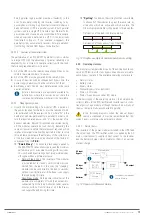
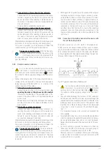
All of the connections mentioned can be seen in
and ,
shown
below:
IDIG1 IDIG2 IDIG3
IDIG4
RL1
RL2
RL4
TAMB TBAT EPO
RL3
IDIG
SIGN
GND
SNMP / NIMBUS
USB
RS 232 / 485
COM
RL
COM
NC
NO
IS
Содержание SLC ADAPT2 Series
Страница 1: ...SLC ADAPT2 UNINTERRUPTIBLE POWER SUPPLY USER MANUAL...
Страница 41: ...41 SLC ADAPT 2 UNINTERRUPTIBLE POWER SUPPLY SYSTEM USER MANUAL...
Страница 62: ...62 SALICRU...
Страница 63: ...63 SLC ADAPT 2 UNINTERRUPTIBLE POWER SUPPLY SYSTEM USER MANUAL...

