17
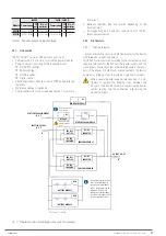
3x400 V
3x208 / 3x220 V
Module Power rating FP
out
No. of
batteries Power rating
FP
out
No. of
batteries
MP10X
10 kVA / 10 kW 1 2x16/../2x22 6 kVA / 5.4 kW 1
2x11
MP15X
15 kVA / 15 kW 1 2x16/../2x22 9 kVA / 8.1 kW 1
2x11
Table 3.
Module power vs input voltage.
4.3.1. Introduction.
The SLC ADAPT2 series of UPS basically consists of:
•
Cabinets with 2, 4 or 6 slots to install the power modules.
•
Power modules, consisting of the following blocks:
AC/DC PFC rectifier.
Battery charger.
DC/AC inverter.
Digital control.
•
Centralised bypass module: control of UPS and parallel pa-
rameters.
•
Maintenance bypass (optional).
•
Control panel with touch screen (see section 7 for more in-
formation).
•
Batteries (Number, type and location depending on the
back-up time).
•
Self-supporting 24, 33 and 42U cabinets to hold the dif-
ferent power modules.
4.3.2. Architecture.
4.3.2.1. Structural diagram.
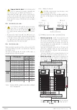
, by way of example, shows a single-line diagram of the device
with three-phase input and output.
All UPS units are structured according to the same criteria, with
separate terminals for the PFC-rectifier power supply and the
static bypass. However, unless otherwise requested, the termi-
nals of the phases of both blocks are connected in the factory
by means of bridging strips to provide a single common input.
When separate power supplies are required, it is ob-
ligatory to remove the bridging strips between the
phases of the two blocks before connecting the power
cables, leaving only the connection strip joining the
neutral terminals.
STATIC BYPASS MODULE
DC / AC
INVERTER
MANUAL BYPASS (*)
REC / PFC
BAT / DC
DC / DC
INVERTER
BYPASS
STATIC BYPASS LINE INPUT
-R, S, T-
N
POWER MODULE # 1
DC / AC
INVERTER
REC / PFC
BAT / DC
DC / DC
INVERTER
POWER MODULE #N
•
•
•
OUTPUT U, V, W
N
BATTERY MODULE
BCB
BATTERY MODULE
BCB
Connection strips
between phases for
mains.
Q1
Q2
INLET LINE OF UPS
-R, S, T-
Not installed on 6 and
8-slot sub-racks.
The batteries are represented
in the structural diagram as
they are an essential part of
an UPS. The batteries can be
supplied in the same rack
cabinet, in a separate cabinet,
in a rack, or not supplied if the
customer already has them.
(*) External or optional
Fig. 11.
Single-line structural diagram by way of example.
SLC ADAPT 2
- UNINTERRUPTIBLE POWER SUPPLY SYSTEM
-
USER MANUAL
Содержание SLC ADAPT2 Series
Страница 1: ...SLC ADAPT2 UNINTERRUPTIBLE POWER SUPPLY USER MANUAL...
Страница 41: ...41 SLC ADAPT 2 UNINTERRUPTIBLE POWER SUPPLY SYSTEM USER MANUAL...
Страница 62: ...62 SALICRU...
Страница 63: ...63 SLC ADAPT 2 UNINTERRUPTIBLE POWER SUPPLY SYSTEM USER MANUAL...


