37
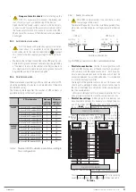
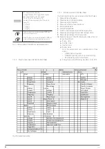
UPS mains
input
UPS
Output
Input line
To loads
External manual bypass board, with common input network for
rectifier and static bypass.
To the UPS J5
terminal block
External manual bypass board with separate networks for
rectifier and static bypass.
UPS mains
input
UPS bypass
input
UPS
Output
AC1 line
input
AC2 line
input
To loads
To the UPS J5
terminal block
Fig. 31.
Internal wiring diagram of an external manual
bypass board for a device.
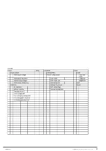
Functionality of the switches:
Input circuit breaker.
Static bypass circuit breaker - line 2.
Output circuit breaker.
Manual bypass circuit breaker -maintenance Bypass-.
It is necessary to connect the auxiliary contact of the manual
bypass switch on the external panel, with the J5 terminal
block of the communication block of the UPS as a preven-
tive action. In case of improper or untimely switching of
the manual bypass switch to “On” with the UPS in “Normal
Mode”, this auxiliary contact will force the transfer of the
device to “Bypass Mode”, so avoiding a short-circuit and its
destructive consequences.
If you are purchasing a manual bypass board, you must en-
sure that you have the auxiliary contact normally open -NO-
which should be advanced to the closed position.
In parallel systems, the manual bypass mechanism shall
have as many auxiliary contacts as there are units in par-
allel, allowing separate connection.
6.6. OPERATING INSTRUCTIONS FOR MAINTENANCE OF
POWER MODULES.
These actions are reserved exclusively for the
T.S.S.
staff or
the distributor.
6.6.1. Maintenance guide for power modules.
6.6.1.1. With the system operating in normal mode and the
normal bypass voltage and frequency, with at least 1
power module as redundant:
1.
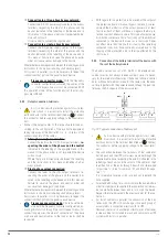
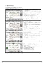
Click on the
icon in the “Status & Ops” menu to
enable the power module shut-down function.
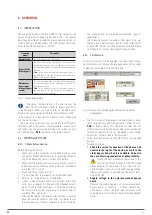
2.
Using the “On/Off” button next to the LED indications on
the front panel, manually stop the power module. Use an
object of diameter ≤ 3 mm, such as a small screwdriver,
to insert it into the hole indicated as “ ” and press for
around 5-6 seconds on the button located on the inside.
3.
Remove the fixing screws of the lateral trim profiles and
the power module fixing screws.
Slightly pull the handle on each end of the module and re-
move it 4-5 cm from the socket to remove it from the con-
nector on the backplane of the device.
Wait around 10 minutes and remove it from its slot.
To ensure safety, check with an instrument the voltage
of the DC bus, which should be below 60 V DC.
6.6.1.2. No power modules operating as redundant:
1.
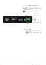
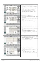
Click on the icon
BYP Transf.
in the “Operation” menu. to
switch to “Bypass mode.”
2.
Click on the icon
in the “Operation” menu to
enable the power module shutdown function.
3.
Manually stop the power module by pressing the button
“ ” for around 5-6 sec.
4.
Remove the fixing screws of the lateral trim profiles and
the power module fixing screws.
Slightly pull the handle on each end of the module and re-
move it 4-5 cm from the socket to remove it from the con-
nector on the backplane of the device.
Wait around 10 minutes and remove it from its slot.
To ensure safety, check with an instrument the voltage
of the DC bus, which should be below 60 V DC.
5.
After the end of the maintenance operations, insert the
power module until it is at the end of its slot to connect
to the “backplane” of the device. After around 2 min the
power module will activate automatically adding to the par-
allel of the rest of the modules.
6.
Insert and tighten the fixing screws of the module.
7.
Fit the side profiles, their screws, and fix them in place.
SLC ADAPT 2
- UNINTERRUPTIBLE POWER SUPPLY SYSTEM
-
USER MANUAL
Содержание SLC ADAPT2 Series
Страница 1: ...SLC ADAPT2 UNINTERRUPTIBLE POWER SUPPLY USER MANUAL...
Страница 41: ...41 SLC ADAPT 2 UNINTERRUPTIBLE POWER SUPPLY SYSTEM USER MANUAL...
Страница 62: ...62 SALICRU...
Страница 63: ...63 SLC ADAPT 2 UNINTERRUPTIBLE POWER SUPPLY SYSTEM USER MANUAL...

