background image

Page vi

Safety Instructions

Most companies have a code of practice for their employees which is designed to ensure their safety in the
working environment.  When new equipment is introduced it is important that operators, maintenance engineers
and supervisors are aware of the potential hazards.

The following guidelines must be followed by any person concerned with the operation, installation or handling
of the detector to ensure correct operation and to avoid any damage to the detector or to the person concerned.

WARNING

The equipment should only be used in accordance with the instructions given herein. Failure to comply
with these instructions may lead to the protection provided by the equipment becoming impaired.
Safeline will not be liable for incidental or consequential damage if the equipment is not installed in
accordance with the instructions given.

WARNING

On no account should any of the electrical panels of your detector be opened by anyone other than a
qualified electrical engineer.  Voltages in excess of 30 volts rms or 50 volts DC. can, in certain
circumstances be lethal.   When working on electrical or electronic equipment always follow current
health and safety practices and observe all other applicable regulations.

!

CAUTION

For correct operation and to prevent any damage to the detector follow the instructions given in this
document under the heading 'Installation'.

!

CAUTION

In accordance with EN 61010-1:1993 this equipment has been designed to be safe at least under the
following conditions:

Indoor use.

Altitude up to 2000m.

Storage temperature:     -10 

°

C to +50 

°

C (15 

°

F to 120 

°

F)

Operating temperature:  -10 

°

C to +45 

°

C (15 

°

F to 110 

°

F)

Maximum relative humidity 93% for temperatures up to 45

°

C.

For connection to TN (EN60950:1992) power distribution systems only, for connections to other power
distribution systems please contact your supplier.

Mains supply voltage fluctuations not to 10%/-15% of the nominal voltage.

Transient overvoltages according to INSTALLATION CATEGORY III.

Pollution degree 2 in accordance with IEC 664.

Содержание STANDARD SERIES

Страница 1: ...Reference number 4618 007 STANDARD SERIES METALDETECTORS INSTRUCTION MANUAL FIRMWARE 2 01 TO 2 49 SAFELINE LTD MONTFORD ST SALFORD ENGLAND Tel 44 0 161 848 8636 Fax 44 0 161 888 2292 Supplied by...

Страница 2: ...n dependent parameters 5 Communicate with the detector using serial communications 6 Arrange a maintenance schedule using the printer option This manual is NOT intended as either 1 A Service Manual al...

Страница 3: ...ge of this document If the owner of the manual has any comments or suggestions as to the form content or presentation of this manual then they should write their suggestions and send them to the Techn...

Страница 4: ...note of extra importance CAUTION This manual is regarded as an integral part of the detector This manual must always be kept with the detector for the whole of its operating life This manual includes...

Страница 5: ...rrect way to lift and support the detector during transportation CORRECT INCORRECT Safeline does not recommend the lifting or supporting of the detector by a person Always use suitable lifting or supp...

Страница 6: ...nels of your detector be opened by anyone other than a qualified electrical engineer Voltages in excess of 30 volts rms or 50 volts DC can in certain circumstances be lethal When working on electrical...

Страница 7: ...Inverters and variable speed drives in the proximity of the detector are installed in full accordance with their manufacturers instructions Where possible avoid placing any cables from Inverters vari...

Страница 8: ...on if they adhere to the conveyor belt To minimise the chance of this occurring a Avoid any operations that may cause metal fragments to come into contact with the conveyor belt e g welding metal dril...

Страница 9: ...ents 38 Speed Sensor Electrical Connections 38 Producing A Rotary Encoder Using A Proximity or Photo electric Sensor 38 Disc Construction 39 Determining The Required Shift Distance Of The Speed Sensor...

Страница 10: ...djustment 4 5 Metal Free Zone Guidelines Standard Series Detectors 5 6A Layout of Components and Terminals for P S Connection PCB issues 6 and 7 8 6B Power connections 9 6C Cable Gland Assemblies for...

Страница 11: ......

Страница 12: ...nge without notice All efforts have been made to ensure the accuracy of this manual However should any error be detected Safeline would greatly appreciate being informed of them The above notwithstand...

Страница 13: ...tch on 5 seconds typical Internal Battery Backup Cell life 5 years Discharge time 6 months from power off at temp of 20 O C Product speed Selectable high and low from the control panel low x 1 high x...

Страница 14: ...ence in sensitivity measured at the centre of the aperture and the sensitivity at any other point in the aperture not closer than 10 mm to the surface Environmental Protection Painted version IP66 NEM...

Страница 15: ...se angle of signals from the coil system For example If we say stainless steel has a particular value of phase angle the phase angle is the angle relative to vibration Reasons for selecting vibration...

Страница 16: ...phase setting Fig 3 Fig 4 It can be seen from Fig 4 that the effects of unwanted signals may be minimised by aligning the phase discrimination with the unwanted signal such as product signals When ali...

Страница 17: ...the magnetic field from the aperture of the detector It is the effect of the leakage magnetic field on the surrounding metalwork that may influence the detectors performance and can give rise to spasm...

Страница 18: ...sections A welded construction is an example of a permanently closed loop Any items bolted to the conveyor frame particularly items positioned across the conveyor e g guards potentially create loops T...

Страница 19: ...ude the two connectors for terminals 57 to 74 However all other connectors for terminals 1 to 56 remain the same allowing earlier P S Connection PCB units to be used providing the user does not requir...

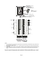
Страница 20: ...52 53 54 55 56 20 21 22 23 24 25 26 27 28 PACK SENSOR SPEED SENSOR RCU SENSOR DETECTOR HEAD CABLE CONNECTIONS RED BLACK WHITE BLUE BROWN PURPLE SPARE YELLOW TURQUOISE ORANGE GREEN GREY PINK BLUE RED B...

Страница 21: ...x 0 2 mm CURRENT RATING 6 AMP COLOURS BROWN LIVE BLUE NEUTRAL GREEN YELLOW EARTH 2 a RECOMMENDED CIRCUIT BREAKER DOUBLE POLE CURRENT RATING 3 AMP OR 4 AMP TYPE C CIRCUIT BREAKER TO BE MOUNTED CLOSE T...

Страница 22: ...Figure 6C Cable Gland Assemblies for Power Supply Unit Page 9A...

Страница 23: ...Figure 8 Bearing Block Insulation Figure 7 Roller Shaft Insulation one end only Page 9B...

Страница 24: ...THIS PAGE IS LEFT BLANK INTENTIONALLY Page 9C...

Страница 25: ...Page 10...

Страница 26: ......

Страница 27: ...ot altered Changing the metal detection characteristics can only be achieved by gaining access to the metal detectors computer Access is restricted by the use of a four digit pass code access code Dif...

Страница 28: ...memory Soft keys Controlled by the software the function of these keys will vary dependent upon the page display OPERATING AND ACCESS MODES Running Mode This represents the normal running display of...

Страница 29: ...ne time To expand the display capabilities a page display menu system is used This can be compared to the pages of a book When there is more than one page of information to be displayed an etc prompt...

Страница 30: ...s used to control the movement of the cursor bar when changing the setting of a digital value A small cursor bar will appear under the active digit on the LCD display when a parameter is available for...

Страница 31: ...memory Each pro gramme is identified by a product number For each programme the various settings are entered or programmed in one of the three access modes Sensitivity Sens A digital value between 00...

Страница 32: ...s feature can only be selected when using a gated timer Power Drive Power Drive A digital value between 0 and up to a maximum of 255 this maximum value will vary from head to head which represents the...

Страница 33: ...rm buzzer will sound when metal is detected if set to On CHANGE MODE Operator Supervisor Engineer QA Inspector access code may be changed as required DETECTOR SPEED Hi Lo select to suit product throug...

Страница 34: ...ocal Printer Unit LPU If software SW handshake is selected the Module uses X ON and X OFF flow control Normally set to hardware HW handshake To programme any of the above facilities enter the Engineer...

Страница 35: ...on would be dependent upon the position of the metal contaminant in the pack and hence be more variable in operation NOTE At high product throughput rates the responce time of the reject relay typical...

Страница 36: ...y be achieved from the Engineers Mode To programme the timer setting 1 Enter the Engineer Access Code 2 Press ETC key display reads Select Timer ABC 3 Select type A B or C display reads Timer x Update...

Страница 37: ...set up the timer Three different timer settings are available ie A B and C to accommodate variations in pack length Delay Time Delay time is the time taken for a metal contaminant to travel from the m...

Страница 38: ...fore Press the Reject Time soft key and adjust the Reject Time until the metal contaminated pack is rejected accurately and consistently If the product is loose adjust the Reject Time so that metal sa...

Страница 39: ...s the pack length at normal conveyor speed This time setting is derived automatically in the set up process Sync Delay Sync delay is the time taken for the pack to travel from the photo beam to the op...

Страница 40: ...ugh the detector and adjust the sensitivity so that the bar graph indicates 2 to 3 red bars 4 Press ETC soft key the display reads Select Timer A B C 5 Select timer A B or C display now reads Timer x...

Страница 41: ...chanism also the detection lamp and buzzer will operate continuously Repeatedly pass a sample pack along the conveyor and adjust the sync delay time so that the pack is rejected accurately and consist...

Страница 42: ...the centre line of the conveyor b The sensitivity should be adjusted such that the metal test piece is only just detected i e 2 or 3 red bars illuminated on the bar graph display c The metal test pie...

Страница 43: ...Gated Yes No No completes the programming and will display the type ot timer Set Updated for a period of five seconds after which it returns to the main menu Setting Up Timer Type tm3 G Gated Mode To...

Страница 44: ...fter which RUN Appears With run displayed pass a pack of the correct size and orientation along the conveyor making sure that it is square on to the conveyor or with a skew angle typical for the line...

Страница 45: ...efore finally entering the data into memory When satisfactory settings have been achieved Press ENTER once again The display will show the type of timer Set Updated for a period of five seconds after...

Страница 46: ...at product is continually moving through the detector aperture in its usual manner NB The detector will not operate correctly with product stationary in the aperture Worst case product effect conditio...

Страница 47: ...sitivity setting without having to re adjust the phase setting Minimising Product Effect Signal without the Use of Phase Discrimination 1 Ensure product is flowing through the detector creating worst...

Страница 48: ...always necessary an even more precise null point will be found by now using the units digit in a similar manner to the tenths digit as described in 9 Using the units digit adjust the phase setting up...

Страница 49: ...at different conveyor speed that necessitate different reject timer setting The settings of timers A B and C are set by the Engineer when the detector is configured At this stage the objective is to...

Страница 50: ...g to the metal detector performance it will date and time stamp events such as rejections and changes made to the metal detector settings The LPU is a very useful management tool for recording events...

Страница 51: ...w a time interval of up to 8 59 between shift reports Setting the time to 0 00 disables timed shift reports Shift Report Start Time Shift Report Start H M W Firmware 2 10 or qreater The start time of...

Страница 52: ...gh the sample or contaminated pack Also refer to Sample Size on Page 21 to ensure that the correct size sample is used Carrying out a performance check The test sample s should be passed though the me...

Страница 53: ...eads PRINT ALL SETTINGS PRINT SHIFT REPORT c Select PRINT SHIFT REPORT c If nothing further is required press the PROG EXIT key to return to the running mode 3 If the accumulated shift report informat...

Страница 54: ...ed sensor must be the same output type NPN or PNP Output Voltage 15 V minimum Output Current 10 mA minimum Output Waveform Pulse output Pulse width 10 ms minimum Frequency 50 Hz maximum Speed Sensor E...

Страница 55: ...y the detector i e its resolution Table A 1 can be used to determine the shift distance for your system Using distance d between the detection and rejection points see Figure A 3 below follow these st...

Страница 56: ...t distance is 19 mm At this point distance d still lies within limits and we have an improved maximum conveyor speed at the expense of a larger shift distance If your maximum conveyor speed still exce...

Страница 57: ...s default value and the 21st to 25th segment of the bar graph display is flashed to warn the user The metal detector is not prevented from operating The flashing segments of the bar graph are cleared...

Страница 58: ...R FAULT MESSAGES BALANCE FAULT CONTACT SUPPLIER This message on the LCD prevents the metal detector from operating and forces a reject condition If a Reject Confirmation Unit RCU is fitted and operati...

Страница 59: ...mation being output by the metal detector is in columns of up to 42 characters This means that for optimum appearance and clarity your printer should be 42 columns or greater The serial communication...

Страница 60: ...od practice to connect these signals together as shown 2 The printer pin numbers shown are for an RS232 25 way D type connector if your printer uses a 9 way D type connector consult the printer manual...

Страница 61: ...A 01 195 0000 B 02 180 0000 A 03 180 0000 A 04 180 0000 A 05 180 0000 A 06 180 0000 A 07 180 0000 A 08 180 0000 A 09 180 0000 A 10 180 0000 A 11 180 0000 A 12 180 0000 A 13 180 0000 A 14 180 0000 A 15...

Страница 62: ...Prod No 01 Sens 156 Phase 3100 Timer B Rej Count RESET Pack Count RESET Current Prod No 00 QA Settings Line ID 0205 Printer YES Relay Rpt YES Settings Rpt YES Report Int 8 00 Test Int 2 00 Overdue Int...

Страница 63: ...56 Phase 3100 Timer B Material FERROUS Size 1 5mm Dtection YES Reject Rly YES Result PASSED Material STAINLESS STEEL Size 1 8mm Dtection YES Reject Rly YES Result PASSED Date Time 01 Jan 1998 09 01 15...

Страница 64: ...them as discrete products Presentation of the product must be consistent product guides may be needed Up to 5 correctly presented products may be in the aperture at any one time If any one of the abov...

Страница 65: ...ion Once PSC is setup and working if required SENS can be manually adjusted but PHASE cannot If PHASE is adjusted PSC will stop working and the P in PHASE will stop flashing Firmware Version 2 15 or g...

Страница 66: ...ervisors Mode Page 51 Flow Chart Engineers Mode Page 52 Flow Chart QA Operator Mode Page 54 Flow Chart QA Inspector Mode Page 55 Flow Chart Auto setup Routine Page 56 Flow Chart tm1 Timer Page 57 Flow...

Страница 67: ...S PROD No ETC PHASE Pack Count ETC Reject Count Product Number 00 PROG EXIT Enter security code Access Modes Product Number 01 to 20 RUNNING MODE FLOW CHART VERSION 2 01 to 2 49 ETC Current Time ETC N...

Страница 68: ...2 49 RUNNING MODE PROG EXIT ENTER OPERATOR CODE ETC PROG EXIT SENS PROD No PHASE SENS PROD No PHASE Full Access sensitivity adjustable Limited Access Sensitivity not adjustable ENTER ENTER ETC ETC Pa...

Страница 69: ...E ETC PROG EXIT ENTER SUPERVISOR CODE ENTER ETC ETC ETC ETC ETC PROG EXIT SELECT TIMER A B C REJECT COUNT RESET Product AUTOMATIC Adjustment MANUAL ETC ETC To Auto setup Sub routine PACK COUNT RESET C...

Страница 70: ...DETECT YES NO ETC ETC PACK COUNT RESET ETC ETC OPERATOR ACCESS FULL LIMITED REJECT COUNT RESET POWER DRIVE ENTER ETC ADJUST REFERENCE PHASE SEE OPERATING MANUAL PRIOR TO ADJUSTMENT REFERENCE PHASE SE...

Страница 71: ...SH FRENCH GERMAN SPANISH DUTCH ITALIAN SWEDISH D NISH JAPANESE Extension time becomes window time when atm3 or tm3G timer is selected NEW CODE CONTINUED FROM LAST PAGE A B C CHANGE CODE OPERATORS QA I...

Страница 72: ...E FLOW CHART VERSION 2 01 to 2 49 PROG EXIT ENTER QA OPERATOR CODE ETC ETC EXIT FERROUS FERROUS NONE FERROUS NONE FERROUS Pass mm Fe NFe SS sample PASSED FAILED PACK COUNT REJECT COUNT CURRENT TIME NE...

Страница 73: ...VERSION 2 22 OR GREATER LINE ID ETC Printer YES NO FERROUS NON FERROUS STAINLESS STEEL ENTER EETC SHIFT REPORT OPTIONS Reject Relay operations IN OUT Modified Settings IN OUT Shift Report Int H M Firm...

Страница 74: ...ode Please wait Pass product through aperture Adjusting phase Product signal too large Please wait Product signal too large Please wait Product signal too large Please wait Please wait Pass product th...

Страница 75: ...TIMER A B C UPDATE NO TIMER A B C UPDATE NO TIMER TYPE tm3 g See separate sub routine TIMER TYPE tm2 g TIMER TYPE tm1 g tm1 REJECT TIME ENTER TIMER A B C TYPE tm1 SET UPDATED Return to main menu tm 1...

Страница 76: ...TE YES TIMER TYPE tm3 g TIMER TYPE tm2 g TIMER TYPE tm1 See separate sub routine See separate sub routine GATED TIMER STILL YES REQUIRED NO tm2 g SIGNAL DELAY tm2 g REJECT TIME ENTER tm2 g GATED YES t...

Страница 77: ...A B C UPDATE YES TIMER TYPE tm3 G TIMER TYPE tm2 G TIMER TYPE tm1 See separate sub routine GATED TIMER STILL YES REQUIRED NO tm3 G SIGNAL SHIFT tm3 G REJECT SHIFT ENTER tm3 G GATED YES tm3 G GATED NO...

Страница 78: ...Page 60 TYPICAL METAL DETECTOR CONVEYOR...

Страница 79: ...cables should be grounded at suitable intervals where possible 4 Remove insulation only where screening clamps are shown to provide good earth continuity at that point 5 Do not run the power cables I...

Страница 80: ...inspection of plastic and gasket materials should be made to ensure no wear or damage has occurred that may affect the ingress integrity of the system The power supply module enclosure can in some ca...

Страница 81: ...non metallic parts with a dry cloth CAUTION Refer to manual for connection details ACHTUNG Vor inbetriebnahme bedienanleitung beachten Voir le manuel ATTENTION CAUCION avant tout cablage por conection...

Отзывы: