Page 7
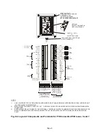
connections and the position and rating of the
recommended circuit breaker are shown in Fig. 6B.
Arrangement of the gland assemblies for
connecting the power cable to the power unit box
are shown in Fig. 6C.
NOTE - with reference to Fig. 6A
If the P/S Connection PCB fitted is an earlier unit
(Issue 4 or 5) then it will not include the two
connectors for terminals 57 to 74. However all other
connectors (for terminals 1 to 56) remain the same
allowing earlier P/S Connection PCB units to be
used, providing the user does not require the
functions offered by the missing terminals.
These instructions are for connection to TN
(EN60950:1992) power distribution systems only.
For connections to other power distribution systems
please contact your supplier.
An information booklet is available with more
detailed Guidelines regarding metal detection
conveyor design.
Содержание STANDARD SERIES
Страница 11: ......
Страница 22: ...Figure 6C Cable Gland Assemblies for Power Supply Unit Page 9A...
Страница 23: ...Figure 8 Bearing Block Insulation Figure 7 Roller Shaft Insulation one end only Page 9B...
Страница 24: ...THIS PAGE IS LEFT BLANK INTENTIONALLY Page 9C...
Страница 25: ...Page 10...
Страница 26: ......
Страница 78: ...Page 60 TYPICAL METAL DETECTOR CONVEYOR...


