SOUTHERN AVIONICS COMPANY
Model SA100 Dual
2-20
Theory of Operation, Radiobeacon
2.3.6 Keyer
The Keyer consists of a Keyer Code PWB and one or more Coder Shift Register PWB's. Each
Coder Shift Register PWB is programmed with DIP switches with each switch ON condition
corresponding to a key down for an adjustable time of 60 to 200 ms. The normal keying rate of 8
baud is adjusted at the factory so that a single switch ON condition corresponds to a 125 ms (1
bit) key down period.
Standard characters are: a dot, 1 bit; a dash, 3 bits; space between letters, 3 bits; and space
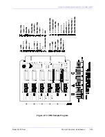
between complete code sequences, 5 bits. See Figure "Example Program for Coder Shift
Register PWB." Each bit is user programmable so that nonstandard coding could be used if
required. A Coder Shift Register PWB can store 47 bits, which is enough for 3 or more letters,
depending on the letter length. For example, one Coder Shift Register PWB can be used for
three J's (.---), or twelve E's (.) If the code requires more than 47 bits, a second Coder Shift
Register PWB is added.
2.3.6.1 Keyer Code
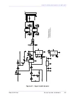
U1C, U1B, R3, R4, R5, and C1 comprise a square wave oscillator with an adjustable frequency
of 6 to 18 Hz. Normal setting is 8 Hz for an 8 baud (125 ms bit) keying rate. This clock signal is
fed to the Coder Shift Register PWB via level shifter U6 and to the clock input of shift register U2.
A key down signal from the Coder Shift Register PWB is at pin 2 of the board, which is level
shifted by U5 and inverted by U1D, applying a 0 to pins 1 and 2 of U2. U1E inverts the 0 and
applies a 1 to Q1 and to the Keyer output, pin 9, via level shifter U6. The 1 at Q1 illuminates DS1
and the 1 at the Keyer output opens the Tone Gate on the Tone Key PWB. When four key up
conditions (0's) are received in sequence, four 1's are loaded into shift register U2, causing the
four outputs to go to 1 and, through U3A, trigger monostable multivibrator U4A. U4A generates a
pulse that clears U2 and sends a load/shift command to the Coder Shift Register PWB at pin3,
via U3B and U6. NOTE: R6 and C2 can be changed to adjust the dead time between identifier
repetitions. U5 and U6 are level shifters added to maintain 12V interboard logic levels.
2.3.6.2 Coder Shift Register PWB
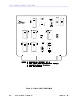
The code sequence is loaded into DIP switches U1 through U6 starting at U1 and working toward
U6. Switch 1 of U1 is always in the open position. If all of these switches are not used, it is
necessary to leave the next 4 switches past the last code bit open. When a load/shift command
is received from the Keyer Code PWB the latched switch information is clocked out serially from
pin 9 of U18 to pin 2 of the Coder Shift Register PWB and to pin 2 of the Keyer Code PWB. At
the end of the code sequence, the four key up conditions (0's) programmed into the switches are
sensed by U2 on the Keyer Code PWB and the sequence is repeated. The four programmed 0's
at the end of the sequence plus the one programmed 0 at the beginning of the sequence create
a five bit space between code sequences. A 0 is loaded into pin 10 of U18 as each bit is shifted
through the chain of shift registers so that if all of the switches are used, there is still a sequence
of 0's at the end of the code sequence. Thus at the end of the sequence, the first four 0's will be
sensed by U2 on the Keyer Code PWB and the sequence will repeat. If two Coder Shift Register
PWB's are used, the Code Train Output of the second PWB (pin 2) is connected to the Code
Extension (pin 22) of the first PWB, doubling the length of the serial connected shift register and
doubling the number of possible bits in the code sequence. U20 and U21 are level shifters added
to maintain 12V interboard logic levels.
Содержание SA100
Страница 20: ...SOUTHERN AVIONICS COMPANY Model SA100 Dual x Contents...
Страница 22: ...SOUTHERN AVIONICS COMPANY Model SA100 Dual 1 2 Introduction This page intentionally left blank...
Страница 24: ...SOUTHERN AVIONICS COMPANY Model SA100 Dual 1 4 Introduction Figure 1 1 Transmitter Enclosure Dimensions...
Страница 25: ...SOUTHERN AVIONICS COMPANY Model SA100 Dual 1 5 Introduction Figure 1 2 Transmitter Portrait...
Страница 26: ...SOUTHERN AVIONICS COMPANY Model SA100 Dual 1 6 Introduction This page intentionally left blank...
Страница 28: ...SOUTHERN AVIONICS COMPANY Model SA100 Dual 1 8 Introduction This page intentionally left blank...
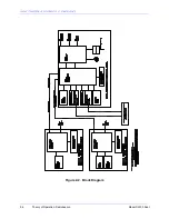
Страница 36: ...SOUTHERN AVIONICS COMPANY Model SA100 Dual 2 6 Theory of Operation Radiobeacon Figure 2 2 Block Diagram...
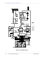
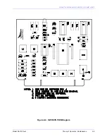
Страница 39: ...SOUTHERN AVIONICS COMPANY Model SA100 Dual 2 9 Theory of Operation Radiobeacon Figure 2 4 KWOSYN PWB Diagram...
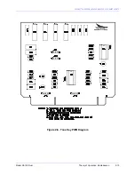
Страница 43: ...SOUTHERN AVIONICS COMPANY Model SA100 Dual 2 13 Theory of Operation Radiobeacon Figure 2 6 Tone Key PWB Diagram...
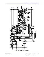
Страница 45: ...SOUTHERN AVIONICS COMPANY Model SA100 Dual 2 15 Theory of Operation Radiobeacon Figure 2 7 Audio PWB Schematic...
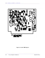
Страница 46: ...SOUTHERN AVIONICS COMPANY Model SA100 Dual 2 16 Theory of Operation Radiobeacon Figure 2 8 Audio PWB Diagram...
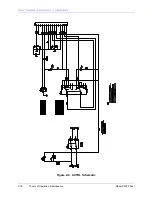
Страница 48: ...SOUTHERN AVIONICS COMPANY Model SA100 Dual 2 18 Theory of Operation Radiobeacon Figure 2 9 ACTRL Schematic...
Страница 49: ...SOUTHERN AVIONICS COMPANY Model SA100 Dual 2 19 Theory of Operation Radiobeacon Figure 2 10 ACTRL Diagram...
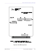
Страница 53: ...SOUTHERN AVIONICS COMPANY Model SA100 Dual 2 23 Theory of Operation Radiobeacon Figure 2 13 CRS Sample Program...
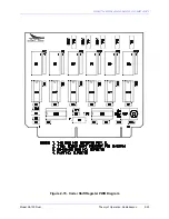
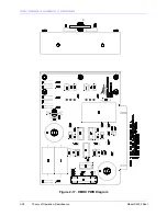
Страница 58: ...SOUTHERN AVIONICS COMPANY Model SA100 Dual 2 28 Theory of Operation Radiobeacon D Figure 2 17 DMOD PWB Diagram...
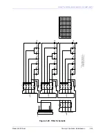
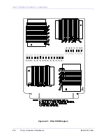
Страница 64: ...SOUTHERN AVIONICS COMPANY Model SA100 Dual 2 34 Theory of Operation Radiobeacon Figure 2 21 Filter PWB Diagram...
Страница 68: ...SOUTHERN AVIONICS COMPANY Model SA100 Dual 2 38 Theory of Operation Radiobeacon Figure 2 24 HWRF PWB Diagram...
Страница 70: ...SOUTHERN AVIONICS COMPANY Model SA100 Dual 2 40 Theory of Operation Radiobeacon Figure 2 26 AMTR Diagram...
Страница 73: ...SOUTHERN AVIONICS COMPANY Model SA100 Dual 2 43 Theory of Operation Radiobeacon Figure 2 29 Monitor PWB Diagram...
Страница 75: ...SOUTHERN AVIONICS COMPANY Model SA100 Dual 2 45 Theory of Operation Radiobeacon Figure 2 31 SA LED PWB Diagram...
Страница 82: ...SOUTHERN AVIONICS COMPANY Model SA100 Dual 2 52 Theory of Operation Radiobeacon Figure 2 37 DCHOKE PWB Diagram...
Страница 105: ...SOUTHERN AVIONICS COMPANY Model SA100 Dual 2 75 Theory of Operation Radiobeacon Figure 2 56 DC Auto Disconnect Diagram...
Страница 110: ...SOUTHERN AVIONICS COMPANY Model SA100 Dual 2 80 Theory of Operation Radiobeacon Figure 2 59 Modem PWB Schematic...
Страница 111: ...SOUTHERN AVIONICS COMPANY Model SA100 Dual 2 81 Theory of Operation Radiobeacon Figure 2 60 Modem PWB Assembly...
Страница 116: ...SOUTHERN AVIONICS COMPANY Model SA100 Dual 2 86 Theory of Operation Radiobeacon This page intentionally left blank...
Страница 119: ...SOUTHERN AVIONICS COMPANY Model SA100 Dual 3 3 Antennas Figure 3 1 Antenna Reactance...
Страница 120: ...SOUTHERN AVIONICS COMPANY Model SA100 Dual 3 4 Antennas This page intentionally left blank...
Страница 122: ...SOUTHERN AVIONICS COMPANY Model SA100 Dual 4 2 Installation and Operation Figure 4 1 Interconnecting Wire Diagram...
Страница 123: ...SOUTHERN AVIONICS COMPANY Model SA100 Dual 4 3 Installation and Operation Figure 4 2 Input Output Terminal Blocks...
Страница 124: ...SOUTHERN AVIONICS COMPANY Model SA100 Dual 4 4 Installation and Operation This page intentionally left blank...
Страница 159: ...SOUTHERN AVIONICS COMPANY Model SA100 Dual 5 7 Maintenance Figure 5 1 Troubleshooting Flow Chart...
Страница 160: ...SOUTHERN AVIONICS COMPANY Model SA100 Dual 5 8 Maintenance This page intentionally left blank...
Страница 162: ...SOUTHERN AVIONICS COMPANY Model SA100 Dual 6 2 Parts List This page intentionally left blank...
Страница 164: ...SOUTHERN AVIONICS COMPANY Model SA100 Dual 6 4 Parts List This page intentionally left blank...
Страница 218: ...SOUTHERN AVIONICS COMPANY Model SA100 Dual 6 58 Parts List This page intentionally left blank...
Страница 220: ...SOUTHERN AVIONICS COMPANY Model SA100 Dual 7 2 Modifications Figure 7 1 EMI Filter Module Schematic...
Страница 221: ...SOUTHERN AVIONICS COMPANY Model SA100 Dual 7 3 Modifications Figure 7 2 EMI Filter Module Diagram...
Страница 224: ...SOUTHERN AVIONICS COMPANY Model SA100 Dual 7 6 Modifications This page intentionally left blank...

