SOUTHERN AVIONICS COMPANY
Model SA100 Dual
2-1
Theory of Operation, Radiobeacon
2 Theory of Operation, Radiobeacon
2.1 Functional Description: SA100
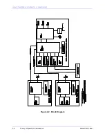
Synthesizer:
The RF signal is generated on the KWOSYN PWB by a voltage controlled LC
oscillator operating at twice the RF frequency. This signal is divided to produce a 1 KHz signal
that is fed to a phase locked loop (PLL) and compared with a 1 KHz signal produced by a divided
4.096 MHz crystal oscillator signal. The PLL voltage controls a tuning diode in the LC oscillator.
The LC oscillator output is divided by two to produce a square wave output at the frequency
dialed in with three rotary switches on the board.
RF Driver:
The square wave output of the synthesizer board is buffered with an inverter on the
EXCITER MOTHERBOARD PWB before being routed to the Power Amplifier input.
Tone Key:
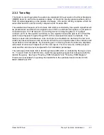
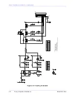
Two separate audio tones, 400 Hz and 1020 Hz, are generated on the TONE KEY
PWB. One of these tones is selected and fed through a gate controlled by the Keyer, a gate
controlled by the AUDIO PWB, and a front panel Modulation Level Control.
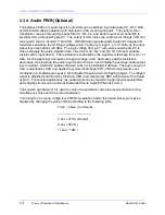
Audio (optional):
Whenever a voice signal is added to the standard beacon signal, it is
processed on the AUDIO PWB. The processing consists of audio filtering, automatic gain control
(AGC), squelch control, and clipping.
Modulator Driver:
The code tone signal, a DC level, and the voice signal are added, buffered,
and level adjusted on the EXCITER MOTHERBOARD PWB before being routed to the modulator
input.
Keyer:
The Keyer consists of a KEYER CODE PWB, and one or two CODER SHIFT
REGISTER PWBs depending on the length of the code. An 8 Hz (adjustable) clock on the
KEYER CODE PWB serially shifts code bits stored on the CODER SHIFT REGISTER PWBs to
the tone gate on the TONE KEY PWB. The code is programmed with DIP switches on the
CODER SHIFT REGISTER PWB in a straightforward manner; ie., a dot is one switch closure, a
dash is three switch closures, space between letters is three switch opens, etc., so that a dot is a
125 msec tone, a dash is a 375 msec tone, etc.
Modulator:
The composite signal from the modulator driver drives a pulse width modulator that
generates a 100 KHz pulse train with pulse widths proportional to the input voltage. These
pulses drive a step down switching regulator which generates the modulating voltage for the
power amplifier.
Power Amplifier:
The half-bridge switching power amplifier amplifies the RF Drive signal and
delivers an amplitude modulated signal with a power level up to 400 watts peak to the filter
module.
Filter:
The filter module covers 190-535 KHz in 5 bands. Bands are selected with jumpers.
Monitor:
The filter output passes through the HWRF PWB to the 50 Ohm RF output. Forward
and reflected power are sampled on this board and used to drive a meter reading for forward
power, reflected power and percent modulation. The forward and reflected power signals are
processed on the MONITOR CTRL PWB to provide shutdown signals for low power, low tone
level, continuous tone, and high reflected power.
Содержание SA100
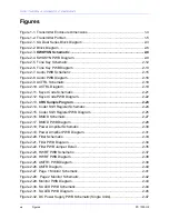
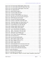
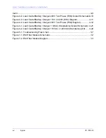
Страница 20: ...SOUTHERN AVIONICS COMPANY Model SA100 Dual x Contents...
Страница 22: ...SOUTHERN AVIONICS COMPANY Model SA100 Dual 1 2 Introduction This page intentionally left blank...
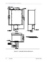
Страница 24: ...SOUTHERN AVIONICS COMPANY Model SA100 Dual 1 4 Introduction Figure 1 1 Transmitter Enclosure Dimensions...
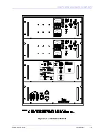
Страница 25: ...SOUTHERN AVIONICS COMPANY Model SA100 Dual 1 5 Introduction Figure 1 2 Transmitter Portrait...
Страница 26: ...SOUTHERN AVIONICS COMPANY Model SA100 Dual 1 6 Introduction This page intentionally left blank...
Страница 28: ...SOUTHERN AVIONICS COMPANY Model SA100 Dual 1 8 Introduction This page intentionally left blank...
Страница 36: ...SOUTHERN AVIONICS COMPANY Model SA100 Dual 2 6 Theory of Operation Radiobeacon Figure 2 2 Block Diagram...
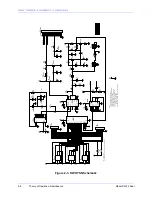
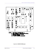
Страница 39: ...SOUTHERN AVIONICS COMPANY Model SA100 Dual 2 9 Theory of Operation Radiobeacon Figure 2 4 KWOSYN PWB Diagram...
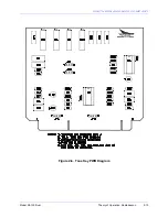
Страница 43: ...SOUTHERN AVIONICS COMPANY Model SA100 Dual 2 13 Theory of Operation Radiobeacon Figure 2 6 Tone Key PWB Diagram...
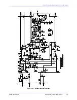
Страница 45: ...SOUTHERN AVIONICS COMPANY Model SA100 Dual 2 15 Theory of Operation Radiobeacon Figure 2 7 Audio PWB Schematic...
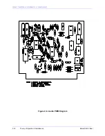
Страница 46: ...SOUTHERN AVIONICS COMPANY Model SA100 Dual 2 16 Theory of Operation Radiobeacon Figure 2 8 Audio PWB Diagram...
Страница 48: ...SOUTHERN AVIONICS COMPANY Model SA100 Dual 2 18 Theory of Operation Radiobeacon Figure 2 9 ACTRL Schematic...
Страница 49: ...SOUTHERN AVIONICS COMPANY Model SA100 Dual 2 19 Theory of Operation Radiobeacon Figure 2 10 ACTRL Diagram...
Страница 53: ...SOUTHERN AVIONICS COMPANY Model SA100 Dual 2 23 Theory of Operation Radiobeacon Figure 2 13 CRS Sample Program...
Страница 58: ...SOUTHERN AVIONICS COMPANY Model SA100 Dual 2 28 Theory of Operation Radiobeacon D Figure 2 17 DMOD PWB Diagram...
Страница 64: ...SOUTHERN AVIONICS COMPANY Model SA100 Dual 2 34 Theory of Operation Radiobeacon Figure 2 21 Filter PWB Diagram...
Страница 68: ...SOUTHERN AVIONICS COMPANY Model SA100 Dual 2 38 Theory of Operation Radiobeacon Figure 2 24 HWRF PWB Diagram...
Страница 70: ...SOUTHERN AVIONICS COMPANY Model SA100 Dual 2 40 Theory of Operation Radiobeacon Figure 2 26 AMTR Diagram...
Страница 73: ...SOUTHERN AVIONICS COMPANY Model SA100 Dual 2 43 Theory of Operation Radiobeacon Figure 2 29 Monitor PWB Diagram...
Страница 75: ...SOUTHERN AVIONICS COMPANY Model SA100 Dual 2 45 Theory of Operation Radiobeacon Figure 2 31 SA LED PWB Diagram...
Страница 82: ...SOUTHERN AVIONICS COMPANY Model SA100 Dual 2 52 Theory of Operation Radiobeacon Figure 2 37 DCHOKE PWB Diagram...
Страница 105: ...SOUTHERN AVIONICS COMPANY Model SA100 Dual 2 75 Theory of Operation Radiobeacon Figure 2 56 DC Auto Disconnect Diagram...
Страница 110: ...SOUTHERN AVIONICS COMPANY Model SA100 Dual 2 80 Theory of Operation Radiobeacon Figure 2 59 Modem PWB Schematic...
Страница 111: ...SOUTHERN AVIONICS COMPANY Model SA100 Dual 2 81 Theory of Operation Radiobeacon Figure 2 60 Modem PWB Assembly...
Страница 116: ...SOUTHERN AVIONICS COMPANY Model SA100 Dual 2 86 Theory of Operation Radiobeacon This page intentionally left blank...
Страница 119: ...SOUTHERN AVIONICS COMPANY Model SA100 Dual 3 3 Antennas Figure 3 1 Antenna Reactance...
Страница 120: ...SOUTHERN AVIONICS COMPANY Model SA100 Dual 3 4 Antennas This page intentionally left blank...
Страница 122: ...SOUTHERN AVIONICS COMPANY Model SA100 Dual 4 2 Installation and Operation Figure 4 1 Interconnecting Wire Diagram...
Страница 123: ...SOUTHERN AVIONICS COMPANY Model SA100 Dual 4 3 Installation and Operation Figure 4 2 Input Output Terminal Blocks...
Страница 124: ...SOUTHERN AVIONICS COMPANY Model SA100 Dual 4 4 Installation and Operation This page intentionally left blank...
Страница 159: ...SOUTHERN AVIONICS COMPANY Model SA100 Dual 5 7 Maintenance Figure 5 1 Troubleshooting Flow Chart...
Страница 160: ...SOUTHERN AVIONICS COMPANY Model SA100 Dual 5 8 Maintenance This page intentionally left blank...
Страница 162: ...SOUTHERN AVIONICS COMPANY Model SA100 Dual 6 2 Parts List This page intentionally left blank...
Страница 164: ...SOUTHERN AVIONICS COMPANY Model SA100 Dual 6 4 Parts List This page intentionally left blank...
Страница 218: ...SOUTHERN AVIONICS COMPANY Model SA100 Dual 6 58 Parts List This page intentionally left blank...
Страница 220: ...SOUTHERN AVIONICS COMPANY Model SA100 Dual 7 2 Modifications Figure 7 1 EMI Filter Module Schematic...
Страница 221: ...SOUTHERN AVIONICS COMPANY Model SA100 Dual 7 3 Modifications Figure 7 2 EMI Filter Module Diagram...
Страница 224: ...SOUTHERN AVIONICS COMPANY Model SA100 Dual 7 6 Modifications This page intentionally left blank...

