SOUTHERN AVIONICS COMPANY
Model SA100 Dual
2-77
Theory of Operation, Radiobeacon
transmission over radio or telephone link. The Modem PWB supplies this data conversion. U1 of
the Modem PWB is a single package modulator-demodulator integrated circuit which converts
the data stream to an audio channel with frequencies of 2025 Hz and 2225 Hz for transmission
from the transmitter to the Remote Control Panel. Control switch positions are transmitted from
the Remote Control Panel to the transmitter site over a second audio channel with frequencies of
1070 Hz and 1270 Hz. The two audio channels are electrically separated. To program a modem
for use in the Local Control Panel, remove Jumper J1 from the Modem Board if it has been
previously installed. Install Jumper J1 for use of the modem in the Remote Radiobeacon Control
Panel. U1 detects the presence or absence of an audio carrier transmitted from the modem
located at the other end of the data link. A carrier detect LED is located on the Modem Board for
diagnostic purposes. It will remain lit whenever a carrier of the proper frequency channel is
received.
Содержание SA100
Страница 20: ...SOUTHERN AVIONICS COMPANY Model SA100 Dual x Contents...
Страница 22: ...SOUTHERN AVIONICS COMPANY Model SA100 Dual 1 2 Introduction This page intentionally left blank...
Страница 24: ...SOUTHERN AVIONICS COMPANY Model SA100 Dual 1 4 Introduction Figure 1 1 Transmitter Enclosure Dimensions...
Страница 25: ...SOUTHERN AVIONICS COMPANY Model SA100 Dual 1 5 Introduction Figure 1 2 Transmitter Portrait...
Страница 26: ...SOUTHERN AVIONICS COMPANY Model SA100 Dual 1 6 Introduction This page intentionally left blank...
Страница 28: ...SOUTHERN AVIONICS COMPANY Model SA100 Dual 1 8 Introduction This page intentionally left blank...
Страница 36: ...SOUTHERN AVIONICS COMPANY Model SA100 Dual 2 6 Theory of Operation Radiobeacon Figure 2 2 Block Diagram...
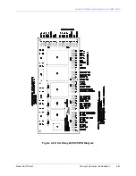
Страница 39: ...SOUTHERN AVIONICS COMPANY Model SA100 Dual 2 9 Theory of Operation Radiobeacon Figure 2 4 KWOSYN PWB Diagram...
Страница 43: ...SOUTHERN AVIONICS COMPANY Model SA100 Dual 2 13 Theory of Operation Radiobeacon Figure 2 6 Tone Key PWB Diagram...
Страница 45: ...SOUTHERN AVIONICS COMPANY Model SA100 Dual 2 15 Theory of Operation Radiobeacon Figure 2 7 Audio PWB Schematic...
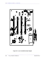
Страница 46: ...SOUTHERN AVIONICS COMPANY Model SA100 Dual 2 16 Theory of Operation Radiobeacon Figure 2 8 Audio PWB Diagram...
Страница 48: ...SOUTHERN AVIONICS COMPANY Model SA100 Dual 2 18 Theory of Operation Radiobeacon Figure 2 9 ACTRL Schematic...
Страница 49: ...SOUTHERN AVIONICS COMPANY Model SA100 Dual 2 19 Theory of Operation Radiobeacon Figure 2 10 ACTRL Diagram...
Страница 53: ...SOUTHERN AVIONICS COMPANY Model SA100 Dual 2 23 Theory of Operation Radiobeacon Figure 2 13 CRS Sample Program...
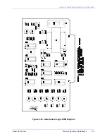
Страница 58: ...SOUTHERN AVIONICS COMPANY Model SA100 Dual 2 28 Theory of Operation Radiobeacon D Figure 2 17 DMOD PWB Diagram...
Страница 64: ...SOUTHERN AVIONICS COMPANY Model SA100 Dual 2 34 Theory of Operation Radiobeacon Figure 2 21 Filter PWB Diagram...
Страница 68: ...SOUTHERN AVIONICS COMPANY Model SA100 Dual 2 38 Theory of Operation Radiobeacon Figure 2 24 HWRF PWB Diagram...
Страница 70: ...SOUTHERN AVIONICS COMPANY Model SA100 Dual 2 40 Theory of Operation Radiobeacon Figure 2 26 AMTR Diagram...
Страница 73: ...SOUTHERN AVIONICS COMPANY Model SA100 Dual 2 43 Theory of Operation Radiobeacon Figure 2 29 Monitor PWB Diagram...
Страница 75: ...SOUTHERN AVIONICS COMPANY Model SA100 Dual 2 45 Theory of Operation Radiobeacon Figure 2 31 SA LED PWB Diagram...
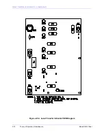
Страница 82: ...SOUTHERN AVIONICS COMPANY Model SA100 Dual 2 52 Theory of Operation Radiobeacon Figure 2 37 DCHOKE PWB Diagram...
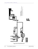
Страница 105: ...SOUTHERN AVIONICS COMPANY Model SA100 Dual 2 75 Theory of Operation Radiobeacon Figure 2 56 DC Auto Disconnect Diagram...
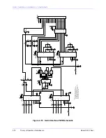
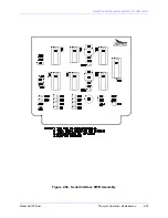
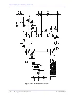
Страница 110: ...SOUTHERN AVIONICS COMPANY Model SA100 Dual 2 80 Theory of Operation Radiobeacon Figure 2 59 Modem PWB Schematic...
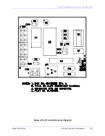
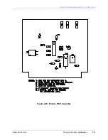
Страница 111: ...SOUTHERN AVIONICS COMPANY Model SA100 Dual 2 81 Theory of Operation Radiobeacon Figure 2 60 Modem PWB Assembly...
Страница 116: ...SOUTHERN AVIONICS COMPANY Model SA100 Dual 2 86 Theory of Operation Radiobeacon This page intentionally left blank...
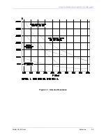
Страница 119: ...SOUTHERN AVIONICS COMPANY Model SA100 Dual 3 3 Antennas Figure 3 1 Antenna Reactance...
Страница 120: ...SOUTHERN AVIONICS COMPANY Model SA100 Dual 3 4 Antennas This page intentionally left blank...
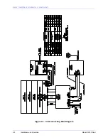
Страница 122: ...SOUTHERN AVIONICS COMPANY Model SA100 Dual 4 2 Installation and Operation Figure 4 1 Interconnecting Wire Diagram...
Страница 123: ...SOUTHERN AVIONICS COMPANY Model SA100 Dual 4 3 Installation and Operation Figure 4 2 Input Output Terminal Blocks...
Страница 124: ...SOUTHERN AVIONICS COMPANY Model SA100 Dual 4 4 Installation and Operation This page intentionally left blank...
Страница 159: ...SOUTHERN AVIONICS COMPANY Model SA100 Dual 5 7 Maintenance Figure 5 1 Troubleshooting Flow Chart...
Страница 160: ...SOUTHERN AVIONICS COMPANY Model SA100 Dual 5 8 Maintenance This page intentionally left blank...
Страница 162: ...SOUTHERN AVIONICS COMPANY Model SA100 Dual 6 2 Parts List This page intentionally left blank...
Страница 164: ...SOUTHERN AVIONICS COMPANY Model SA100 Dual 6 4 Parts List This page intentionally left blank...
Страница 218: ...SOUTHERN AVIONICS COMPANY Model SA100 Dual 6 58 Parts List This page intentionally left blank...
Страница 220: ...SOUTHERN AVIONICS COMPANY Model SA100 Dual 7 2 Modifications Figure 7 1 EMI Filter Module Schematic...
Страница 221: ...SOUTHERN AVIONICS COMPANY Model SA100 Dual 7 3 Modifications Figure 7 2 EMI Filter Module Diagram...
Страница 224: ...SOUTHERN AVIONICS COMPANY Model SA100 Dual 7 6 Modifications This page intentionally left blank...

