SOUTHERN AVIONICS COMPANY
Model SA100 Dual
4-31
Installation and Operation
4.
CAREFULLY increase power with RF LEVEL until REFL is up to the desired shut-
down level as determined above.
5.
Slowly adjust the autoshutdown VSWR ADJ R2 CCW on the Monitor PWB until the
VSWR LED is illuminated, see figure "Monitor PWB Schematic and "Monitor PWB Dia-
gram." Turn RF LEVEL fully CCW. Press RST and slowly increase RF LEVEL while
observing REFL. Transmitter should shut down at desired set level.
6.
Reconnect the RF cable.
7.
Adjust RF LEVEL for the desired carrier power. Set MODE switch to IDENT. If
VSWR shutdown occurs, turn R2 ADJ 1/2 turn CW and push RESET. Continue this pro-
cess until the system does not shutdown and then turn R2 ADJ 1/2 more turn CW.
4.8.4 Monitor Adjustment-Voice System
1 Place the MODE switch in CARR.
2 Apply power to the transmitter.
3 Adjust RF power to the desired shutdown level.
4 Connect a voltmeter to TP3 on the Monitor PWB.
5 Rotate R6 and R22 located on the Monitor PWB fully CCW.
6 Rotate R6 CW until the meter deflects up to approximatly 5.5V.
7 Place the RF METER switch in FRWD and adjust the power output to the desired carrier
level.
8 Place the MODE switch in the CONT (continuous tone) position.
9 Apply the audio line input signal to the transmitter.
10 Check that the average meter deflection in AUDIO is between 1/2 and full scale. If not, adjust
R6 on the Audio PWB.
11 Rotate Code Tone Shutdown Level Control R22 on the Monitor PWB CW until the voltage at
TP3 of the Monitor PWB deflects upward and holds steady.
4.8.5 Monitor Adjustment-Nonvoice System
1 Apply power to the transmitter.
2 Adjust RF power from the transmitter to the desired shutdown level using RF LEVEL Control.
3 Connect voltmeter to TP3 on Monitor PWB.
4 Rotate R6 and R22 located on the Monitor PWB fully CCW.
Содержание SA100
Страница 20: ...SOUTHERN AVIONICS COMPANY Model SA100 Dual x Contents...
Страница 22: ...SOUTHERN AVIONICS COMPANY Model SA100 Dual 1 2 Introduction This page intentionally left blank...
Страница 24: ...SOUTHERN AVIONICS COMPANY Model SA100 Dual 1 4 Introduction Figure 1 1 Transmitter Enclosure Dimensions...
Страница 25: ...SOUTHERN AVIONICS COMPANY Model SA100 Dual 1 5 Introduction Figure 1 2 Transmitter Portrait...
Страница 26: ...SOUTHERN AVIONICS COMPANY Model SA100 Dual 1 6 Introduction This page intentionally left blank...
Страница 28: ...SOUTHERN AVIONICS COMPANY Model SA100 Dual 1 8 Introduction This page intentionally left blank...
Страница 36: ...SOUTHERN AVIONICS COMPANY Model SA100 Dual 2 6 Theory of Operation Radiobeacon Figure 2 2 Block Diagram...
Страница 39: ...SOUTHERN AVIONICS COMPANY Model SA100 Dual 2 9 Theory of Operation Radiobeacon Figure 2 4 KWOSYN PWB Diagram...
Страница 43: ...SOUTHERN AVIONICS COMPANY Model SA100 Dual 2 13 Theory of Operation Radiobeacon Figure 2 6 Tone Key PWB Diagram...
Страница 45: ...SOUTHERN AVIONICS COMPANY Model SA100 Dual 2 15 Theory of Operation Radiobeacon Figure 2 7 Audio PWB Schematic...
Страница 46: ...SOUTHERN AVIONICS COMPANY Model SA100 Dual 2 16 Theory of Operation Radiobeacon Figure 2 8 Audio PWB Diagram...
Страница 48: ...SOUTHERN AVIONICS COMPANY Model SA100 Dual 2 18 Theory of Operation Radiobeacon Figure 2 9 ACTRL Schematic...
Страница 49: ...SOUTHERN AVIONICS COMPANY Model SA100 Dual 2 19 Theory of Operation Radiobeacon Figure 2 10 ACTRL Diagram...
Страница 53: ...SOUTHERN AVIONICS COMPANY Model SA100 Dual 2 23 Theory of Operation Radiobeacon Figure 2 13 CRS Sample Program...
Страница 58: ...SOUTHERN AVIONICS COMPANY Model SA100 Dual 2 28 Theory of Operation Radiobeacon D Figure 2 17 DMOD PWB Diagram...
Страница 64: ...SOUTHERN AVIONICS COMPANY Model SA100 Dual 2 34 Theory of Operation Radiobeacon Figure 2 21 Filter PWB Diagram...
Страница 68: ...SOUTHERN AVIONICS COMPANY Model SA100 Dual 2 38 Theory of Operation Radiobeacon Figure 2 24 HWRF PWB Diagram...
Страница 70: ...SOUTHERN AVIONICS COMPANY Model SA100 Dual 2 40 Theory of Operation Radiobeacon Figure 2 26 AMTR Diagram...
Страница 73: ...SOUTHERN AVIONICS COMPANY Model SA100 Dual 2 43 Theory of Operation Radiobeacon Figure 2 29 Monitor PWB Diagram...
Страница 75: ...SOUTHERN AVIONICS COMPANY Model SA100 Dual 2 45 Theory of Operation Radiobeacon Figure 2 31 SA LED PWB Diagram...
Страница 82: ...SOUTHERN AVIONICS COMPANY Model SA100 Dual 2 52 Theory of Operation Radiobeacon Figure 2 37 DCHOKE PWB Diagram...
Страница 105: ...SOUTHERN AVIONICS COMPANY Model SA100 Dual 2 75 Theory of Operation Radiobeacon Figure 2 56 DC Auto Disconnect Diagram...
Страница 110: ...SOUTHERN AVIONICS COMPANY Model SA100 Dual 2 80 Theory of Operation Radiobeacon Figure 2 59 Modem PWB Schematic...
Страница 111: ...SOUTHERN AVIONICS COMPANY Model SA100 Dual 2 81 Theory of Operation Radiobeacon Figure 2 60 Modem PWB Assembly...
Страница 116: ...SOUTHERN AVIONICS COMPANY Model SA100 Dual 2 86 Theory of Operation Radiobeacon This page intentionally left blank...
Страница 119: ...SOUTHERN AVIONICS COMPANY Model SA100 Dual 3 3 Antennas Figure 3 1 Antenna Reactance...
Страница 120: ...SOUTHERN AVIONICS COMPANY Model SA100 Dual 3 4 Antennas This page intentionally left blank...
Страница 122: ...SOUTHERN AVIONICS COMPANY Model SA100 Dual 4 2 Installation and Operation Figure 4 1 Interconnecting Wire Diagram...
Страница 123: ...SOUTHERN AVIONICS COMPANY Model SA100 Dual 4 3 Installation and Operation Figure 4 2 Input Output Terminal Blocks...
Страница 124: ...SOUTHERN AVIONICS COMPANY Model SA100 Dual 4 4 Installation and Operation This page intentionally left blank...
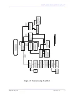
Страница 159: ...SOUTHERN AVIONICS COMPANY Model SA100 Dual 5 7 Maintenance Figure 5 1 Troubleshooting Flow Chart...
Страница 160: ...SOUTHERN AVIONICS COMPANY Model SA100 Dual 5 8 Maintenance This page intentionally left blank...
Страница 162: ...SOUTHERN AVIONICS COMPANY Model SA100 Dual 6 2 Parts List This page intentionally left blank...
Страница 164: ...SOUTHERN AVIONICS COMPANY Model SA100 Dual 6 4 Parts List This page intentionally left blank...
Страница 218: ...SOUTHERN AVIONICS COMPANY Model SA100 Dual 6 58 Parts List This page intentionally left blank...
Страница 220: ...SOUTHERN AVIONICS COMPANY Model SA100 Dual 7 2 Modifications Figure 7 1 EMI Filter Module Schematic...
Страница 221: ...SOUTHERN AVIONICS COMPANY Model SA100 Dual 7 3 Modifications Figure 7 2 EMI Filter Module Diagram...
Страница 224: ...SOUTHERN AVIONICS COMPANY Model SA100 Dual 7 6 Modifications This page intentionally left blank...

