Saberz Project
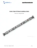
M Chassis Installation Guide
S
HTOK
NPXL
PCB
S
(V
ERSION
V3
SETUP
)
Version 1.9.5_b
–
September 18, 2022
•
Page 13
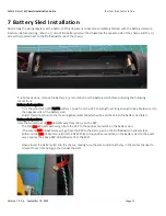
6
Shtok NPXL PCBs (Version V3 setup)
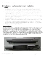
Disclaimer: As with all components, be sure to
reference, study and understand the owner’s manual from the
PCB vendor.
6.1
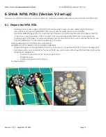
Prepare the NPXL PCBs
-
Carefully sand the outer edges of the NPXL PCB unit to verify fitment into the emitter side of the chassis.
-
If you did not purchase assembled NPXL PCBs you will need to solder the pins onto the PCBs.
-
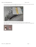
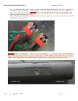
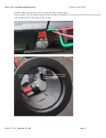
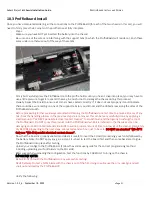
Test-fit the NPXL PCB again (this time with the clear PCB lens on) into the emitter end of the chassis. The PCB
should snap in and stop solidly at the thin raised inner ring which keeps the PCB at the correct placement.
Carefully push the PCB back out using wood dowel or eraser side of a pencil. Be sure to remove the plastic lens
from the PCBs before the next steps of soldering on the wires.
Soldering warning from the PCB vendor (links below):
WARNING! DON’T OVERHEAT THE PCB WHEN SOLDERING!
-
When soldering pins to the Pixel blade connector, make sure to not overheat the PCB, as this will damage pixels.
-
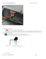
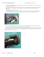
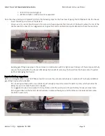
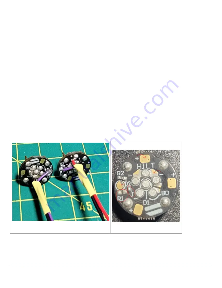
Since there will be no accent LEDs for the metal
“LEDs” seen on the side of the Project M Darth Maul hilt
use the
following V3 configuration:
o
Leave the on-board 330-ohm resistor in place on R2.
o
Bridge the J pad.
o
Remove the resistor on the R1 pad.
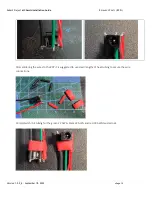
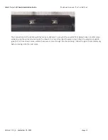
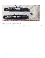
Finished examples: