Introduction Page
3
Document id: 7000 108-011 A2
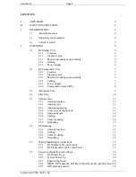
2.8.6 Radio
settings
24
2.8.7
Long Range Settings
25
2.8.8 Alarm
Relay
26
2.8.9
I/O port settings
27
2.8.10 System functional check
29
2.9 Installation
Cables
31
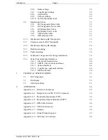
2.9.1
R4 Transponder Data Cable
31
2.9.2
R4 Transponder Power cable
31
2.9.3
R4 Display Data Cable
31
2.9.4
R4 Display Power cable
31
2.9.5
VHF antenna cable
31
2.9.6
GPS antenna cable
31
2.10
Mechanical drawing R4 Transponder
32
2.11
Clearance area for R4 Transponder
33
2.12
Mechanical drawing R4 Display
34
2.13 Desktop
mounting
35
2.14 Panel
mounting
36
2.15
Schematic arrangement for bridge installation
39
2.16 Serial
Communication
Interfaces
40
2.16.1 Electrical
Characteristics
40
2.16.2 ECDIS / Pilot systems interfaces
40
2.16.3 Sensor
interfaces
44
2.16.4 Long Range equipment interface
46
2.16.5 RTCM
interface
50
3 TECHNICAL
SPECIFICATIONS
51
3.1 R4
Transponder
51
3.2 R4
Display
52
3.3
AIS Alarm Relay
53
4 APPENDICES
54
Appendix A.1 – Reference documents
55
Appendix A.2 – Interpretation of IEC 61162-1 Sentences
56
Appendix A.3 – Proprietary Indications (TXT)
62
Appendix A.4 – Proprietary Output Sentences (PSTT)
63
Appendix A.5 – GPS-Cable Selector
64
Appendix A.6 – VHF-Cable Selector
65
Appendix A.7 – Glossary
66
Appendix A.8 – Global Product Support
67
Appendix A.9 – AIS Class A Certificate
68


