background image

Mounting Page 

33 


Document id: 7000 108-011 A2 


2.11 

 Clearance area for R4 Transponder 


Figure 7: Clearance area for R4 Transponder 


Содержание R4-AIS

Страница 1: ...Saab TransponderTech INSTALLATION MANUAL R4 AIS Shipborne Class A Transponder System...

Страница 2: ...riting Saab TransponderTech AB SWEDEN ii Safety instructions Note the following compass safe distances Equipment Compass safe distance m R4 Transponder 0 2 R4 Display Unit 0 6 Saab TransponderTech AB...

Страница 3: ...tatus LED s 8 2 3 AIS Alarm Unit 9 2 4 Pilot Plug 10 2 5 VHF antenna 11 2 5 1 Antenna location 11 2 5 2 Antenna type 11 2 5 3 Antenna separation 11 2 5 4 Clear view of the horizon 12 2 5 5 Antenna hei...

Страница 4: ...anel mounting 36 2 15 Schematic arrangement for bridge installation 39 2 16 Serial Communication Interfaces 40 2 16 1 Electrical Characteristics 40 2 16 2 ECDIS Pilot systems interfaces 40 2 16 3 Sens...

Страница 5: ...please check that the following is included in the delivered package If any of the parts are missing please contact the Saab TransponderTech dealer Standard package Name Qty R4 Display Unit 1 R4 Trans...

Страница 6: ...A System it is recommended to follow the steps as described in this Installation Manual Details of the installation procedure are found in the coming sections of the Installation Manual Recommended in...

Страница 7: ...perature 15 C to 55 C Select a location away from excessive heat sources Avoid areas where there are a high flow of humid salt air Avoid high levels of vibrations and shocks Avoid mounting the R4 Disp...

Страница 8: ...ass Install the R4 Transponder as close as possible to VHF GPS antennas to minimise cable lengths 2 2 2 Clearance area Leave a clearance around the R4 Transponder to facilitate service and installatio...

Страница 9: ...all according to section 2 7 2 2 2 6 Transponder status LED s The green LED indicates that power is applied to the R4 transponder A flashing yellow LED indicates that the R4 Transponder is receiving d...

Страница 10: ...ly the ship s BIIT alarm system may use the alarm messages output on the AIS Presentation Interface PI provided the alarm system is AIS compatible The AIS Alarm Relay is either mounted on a DIN mounti...

Страница 11: ...ect a Personal Pilot Unit PPU This pilot plug should be connected in parallel with the R4 Display pilot plug Use the following plug or physical and electrical equivalent plug Item Type Manufacturer Pa...

Страница 12: ...f the mandatory AIS VHF antenna should be carefully considered Digital communication is more sensitive than analogue voice communication to interference created by reflections in obstructions like mas...

Страница 13: ...short as possible to minimise attenuation of the signal Double shielded coaxial cable equal or better than RG214 is recommended to minimise the effects from electromagnetic interference from high pow...

Страница 14: ...nnas This includes the ship s own AIS VHF antenna if it is designed and installed separately 2 6 2 Cabling To achieve optimum performance the gain of the GPS antenna built in pre amplifier shall match...

Страница 15: ...g to protect against water penetration into the antenna cable Secure the cable properly near the cable ends 2 6 4 Grounding Coaxial down leads must be used for all receiving antennas and the coaxial s...

Страница 16: ...isplay should be connected to the RX lines on the Display port of the R4 Transponder and vice versa The TX lines for the PILOT Plug should however be connected to the TX lines of the PILOT Port on the...

Страница 17: ...should be connected to RX on interfacing equipment and RX on the R4 Transponder should be connected to TX on interfacing equipment Note that the PILOT Plug on the R4 Display is interfaced to the R4 Tr...

Страница 18: ...1162 1 2 Section 2 16 3 should be consulted before doing the installation 2 7 2 4 Long Range The Long Range port should be connected to the Long Range system RX should be connected to the TX on the Lo...

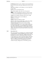
Страница 19: ...ition s Radio settings All parameters are set via the R4 Display To be able to set all parameters when configuring the system Engineering Mode should be activated see 2 8 3 To set the parameters follo...

Страница 20: ...aracters These keys are used when editing messages passwords and so on To write a number just press the key with the right number To write a alphanumerical character press the key with the right chara...

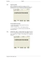
Страница 21: ...ould be displayed Entering Engineering Mode 1 Enter Engineering Mode by pressing the function key Engineering Mode ON 2 Use to select YES or NO and press Enter 3 To set parameters etc follow the steps...

Страница 22: ...select the field to change and press Enter 3 Enter the desired value using the number keys To delete a character use the function key Backspace Press Enter when done 4 Repeat procedures 2 3 for every...

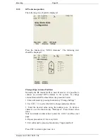
Страница 23: ...the system To change external internal GPS values follow the procedure below 1 Enter edit mode by pressing function key Change Settings 2 Use to select the field to change and press Enter 3 Enter the...

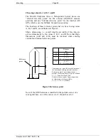
Страница 24: ...atically by the values A B C and D Note that ship s dimensions A B and C D must be identical when entering external and internal reference points Reference point A B D C Distance m A 0 511 B 0 511 C 0...

Страница 25: ...wing view and follow the steps described Press the function key VHF Radio Settings The following view should be displayed Change VHF Radio Parameters 1 Enter edit mode by pressing function key Change...

Страница 26: ...be done The user can set up the R4 to automatically acknowledge or to let the user manually acknowledge any Long Range LR interrogation To change LR Settings start from the following view and follow t...

Страница 27: ...he Alarm Relay view allows the user to turn alarms ON or OFF To do this start from the following view and follow the steps described Press the function key Alarm Relay The following view should be dis...

Страница 28: ...as follows Table 2 1 Port settings Port Name Baudrate 1 PILOT 38400 2 ECDIS 38400 3 LR 9600 4 R4 Display 57600 5 Sensor 1 4800 6 Sensor 2 4800 7 Sensor 3 4800 8 Aux 9600 For the equipment that uses se...

Страница 29: ...iew should be displayed Edit port parameters 1 Enter edit mode by pressing function key Change Settings 2 Use to highlight the data to be changed and press Enter 3 Use to select the value and press En...

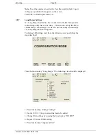
Страница 30: ...he procedure as described below Before doing this check the system must be in Engineering Mode see section 2 8 3 1 Press Mode key and then press function key AIS If the system asks if you want to stay...

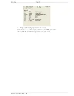
Страница 31: ...Page 30 Document id 7000 108 011 A2 4 Verify that the displayed parameters are correct Note Some of the values may be shown incorrect The reason for this could be that not all sensor ports have been c...

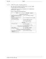
Страница 32: ...ale 2 9 3 R4 Display Data Cable Type 6 Pair x 0 25 mm Shield Wire AWG 24 Length 2000 mm Connector ConXall Maxi Con 18pin female 2 9 4 R4 Display Power cable Type 3 x 0 5 mm2 Wire AWG 20 Length 2000 mm...

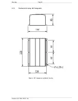
Страница 33: ...Mounting Page 32 Document id 7000 108 011 A2 2 10 Mechanical drawing R4 Transponder Figure 6 R4 Transponder mechanical drawing...

Страница 34: ...Mounting Page 33 Document id 7000 108 011 A2 2 11 Clearance area for R4 Transponder Figure 7 Clearance area for R4 Transponder...

Страница 35: ...Mounting Page 34 Document id 7000 108 011 A2 2 12 Mechanical drawing R4 Display Figure 8 Mechanical Drawing R4 Display...

Страница 36: ...ve to face the direction in which the R4 Display is to be mounted 3 Place the two o rings in the grooves around the screw holes one on each side of the R4 Display Slide the R4 Display into the slots o...

Страница 37: ...he panel mount frame in the rectangular hole and mark the location of the four screw holes in the bedding 4 Remove the panel mount frame and drill four screw holes where marked in the panel 5 Place th...

Страница 38: ...Mounting Page 37 Document id 7000 108 011 A2 Figure 11 Panelmount frame dimensions Figure 12 Panel mount hole dimensions 242 mm 20 55 164 5 256 184...

Страница 39: ...Mounting Page 38 Document id 7000 108 011 A2 Figure 13 Panel mount Figure 14 Clearance distance behind the display...

Страница 40: ...Mounting Page 39 Document id 7000 108 011 A2 2 15 Schematic arrangement for bridge installation Figure 15 Bridge Installation...

Страница 41: ...If needed 1 k line termination resistors can be placed in the terminal block on the input ports 2 16 1 4 Schematics Each of the RS422 serial interfaces on the R4 Transponder fulfils the requirements a...

Страница 42: ...radio range A chart system that fully exploits the transponder features will in addition provide application information communicated by binary messages and text communication possibly by clicking pr...

Страница 43: ...ved in the R4 memory Voyage information Vessel type and cargo category Navigational status Draught max actual static Destination ETA date and time Regional application flags VSD Voyage Static Data Lon...

Страница 44: ...tiated by messages ABM BBM ACA AIR is terminated ABK Acknowledgement message AIS Own ship broadcast data all transmissions available VDO VHF Data link Own vessel message Query response messages ACA AI...

Страница 45: ...ndix A 2 Interpretation of IEC 61162 1 sentences Table 2 4 Sensor input data and formats Sensor Data IEC 61162 1 sentences GNSS Positioning system Time of position Latitude Longitude Accuracy and inte...

Страница 46: ...nder automatically selects the heading source with the highest priority based on the talker identifier of the sensor sentence The priority is according to table below Talker Id Priority HE Highest Pri...

Страница 47: ...information is available If heading information is not available Speed Log data will not be used In this case the R4 Transponder will use the position sensor as source for SOG and COG 2 16 4 Long Ran...

Страница 48: ...y when in EXT APPL mode is made by the display upon reception of confirmation acknowledgement from the external application via the high speed ports The external application acknowledge the interrogat...

Страница 49: ...p s length breadth and type U Number of persons on board W LRF Long Range Function 2 16 4 4 LR output data and formats The output data and formats are in form of four Long Range reply sentences LRF LR...

Страница 50: ...Speed over ground F Destination and ETA I Draught O Ship Cargo P Ship s length breadth and type U Number of persons on board W LRF Long Range Function MMSI of Responder MMSI or Requestor Ship s name...

Страница 51: ...ult it accepts the following RTCM messages Message type 1 Differential GPS Corrections Fixed Message type 2 Delta Differential GPS Corrections Fixed Message type 9 Partial Satellite Set Differential G...

Страница 52: ...kilograms POWER Input Voltage 24 VDC The primary side of the transponder is floating with reference to chassis Current need Transmit 2 3 A 55 W 24 VDC input Receive 0 7 A 16 W 24 VDC input ENVIRONMENT...

Страница 53: ...igma 95 DGPS 30 meters Horizontal 2 sigma 95 GPS The position outputs meets accuracy specification under dynamic conditions of 500 m s and linear acceleration of up to 4g Antenna feeding 5 VDC GPS Ant...

Страница 54: ...Technical Specifications Page 53 Document id 7000 108 011 A2 3 3 AIS Alarm Relay Max switching current 0 1 5 A Max switching voltage 30 VDC 250 VAC Max switching power 1250 VA 150 W...

Страница 55: ...CES A 1 Reference documents A 2 Interpretations of IEC 61162 1 sentences A 3 Proprietary Indications TXT A 4 Proprietary Output Sentences PSTT A 5 GPS cable selector A 6 VHF Cable Selector A 7 Glossar...

Страница 56: ...4 RTCM SC 104 RTCM Recommended Standards for Differential GNSS Service Ref 5 IEC 61993 2 Maritime navigation and radio communication and systems Automatic Identification System AIS Part 2 Class A ship...

Страница 57: ...t UTC Time of GGA or GNS Ignored Expected Error in latitude Ignored Expected Error in longitude Ignored Expected error in altitude Ignored ID number of most likely failed satellite Ignored Probability...

Страница 58: ...Mode with Low Accuracy M Manual Mode with Low Accuracy OTHER No Position GNS GNSS Fix Data If the Mode Indicator is a NULL field the sentence is ignored Field Comment UTC of Position UTC Second is us...

Страница 59: ...UTC Second is used to indicate Time Stamp Status Ignored Latitude 2 fields Used Longitude 2 fields Used SOG knots Used COG degrees Used Date Ignored Magnetic Variation 2 fields Ignored Mode Indicator...

Страница 60: ...red VTG Course Over Ground and Ground Speed Field Comment COG degrees True 2 fields Used COG degrees Magnetic 2 fields Ignored SOG knots 2 fields Used SOG km h 2 fields Ignored Mode Indicator Used ZDA...

Страница 61: ...itude 2 fields Used SW Latitude 2 fields Used SW Longitude 2 fields Used Transitional Zone Size Used Channel A Used Channel A Bandwidth Used Channel B Used Channel B Bandwidth Used Tx Rx Mode Used Pow...

Страница 62: ...ber of filled bits Used SSD Ship Static Data Field Comment Call Sign Used may be NULL Name Used may be NULL Pos Ref A Used to change position reference for the position source in use May be NULL Pos R...

Страница 63: ...Ok 55 Status AIS Channel Management Zone Memory Changed 56 Event Output when the transponder has updated the zone memory AIS Enter Semaphore Mode 61 Status Output when the transponder has become semap...

Страница 64: ...52 30 UTC PSTT 10C Data Link Status This sentence provides information about the traffic on the VHF data link It is output approximately once every 60 seconds Traffic load is calculated over the last...

Страница 65: ...4 95 6 3 RG 223 0 6 5 40 5 5 RG 214 0 35 10 8 18 5 RG 225 0 3 10 9 23 3 For optimum performance of the transponder approximately 10dB gain should be available when the cable attenuation has been subt...

Страница 66: ...d for the VHF antenna connections The cable attenuation shall be kept as low as possible a 3 dB loss is the same as a reduction of the input and output signal to a half Ex A cable of 40 meter RG 214 h...

Страница 67: ...tellite navigation systems such as GPS and GLONASS GPS Global Positioning System IEC International Electro technical Commission LED Light Emitting Diode N A Not Applicable NMEA National Marine Electro...

Страница 68: ...rvice headline Customer Support and Repairs Fill out the Problem Report form and fax mail to us E mail support transpondertech se Telephone support 46 8 627 49 20 Fax support 46 8 627 49 49 For Sales...

Страница 69: ...APPENDICES Page 68 Document id 7000 108 011 A2 APPENDIX A 9 AIS CLASS A CERTIFICATE...

Страница 70: ...APPENDICES Page 69 Document id 7000 108 011 A2...

Отзывы: