background image


Rugby Manufacturing                      1841488C | 13-Jul-20                                       Page 14                               

101010P1010101101010 


Rugby Manufacturing SR-Series Hoist Manual


45° Application Sub-frame Modification 


This section outlines the steps required to convert the standard SR-4016 50° application sub-frame 

into a 45° application sub-frame. Additional modifications to cross-members or other platform/dump 

body components may be required.


1.


Contact Rugby Mfg to order the required kit for this modification: 1867517 - EXTENSION, 45 

DEGREE SF MOD PCBLK.   

2.


Locate the Ø 1/8” x 1-1/2” slot found on the left and right sub-frame channels.   

3.


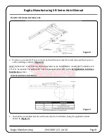
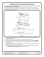
Cut through the left and right sub-frame channels at the cut centerline as shown in 

Figure 16

.   

4.


Insert an extension between the front and rear portion of the sub-frame rails and install the 

1/2” hardware.   

5.


Cut off the excess from the front of the sub-frame channels as applicable to return the sub-frame 

channel to the original 102” overall dimension.   

6.


The sub-frame is now set up for a 45° dump angle. Continue installing the hoist and sub-frame 
per the 

Hoist & Sub-frame Installation 

section of this manual. 


Figure 16


Содержание SR-Series

Страница 1: ...ies hoist sub frame manufactured by Rugby Manufacturing Co This manual should be kept readily accessible for any poten tial operator at all times Should you have any questions or concerns please contact your dealer or a Rugby Manufacturing customer service representative before use Toll Free 1 800 869 9162 Office 1 701 776 5722 Fax 1 701 776 6235 Visit www rugbymfg com for further information Body...

Страница 2: ... Information 1 Serial Number 1 Capacity Chart 2 Torque Values Chart 4 Body Prop Application Chart 4 Hydraulic System 5 Assembly Installation 6 Body Prop Installation 6 Hoist Sub frame Assembly 7 Hoist Sub frame Installation 8 45 Application Sub frame Modification 14 Decal Locations 15 Operation 16 Body Prop Operation 16 Maintenance 16 Diagrams 17 ...

Страница 3: ...r warning and caution It is imperative that all labels are obeyed for the safety of the operator Indicates a hazardous situation which if not avoided will result in death or serious injury Indicates a hazardous situation which if not avoided could result in death or serious injury Indicates a hazardous situation which if not avoided could result in minor or moderate injury Reference Information Se...

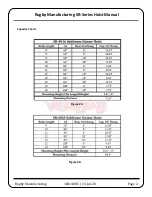
Страница 4: ...Rugby Manufacturing 1841488C 13 Jul 20 Page 2 Rugby Manufacturing SR Series Hoist Manual Figure 2A Figure 2B Capacity Charts ...

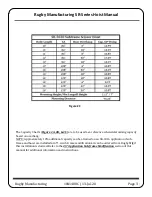
Страница 5: ...etermining capacity based on overhang NOTE Approximately 10 additional capacity can be attained on an SR 4016 application if sub frame and hoist are installed at 45 A sub frame modification kit can be ordered from Rugby Mfg if this installation is desired Refer to the 45 Application Sub frame Modification section of this manual for additional information and instructions ...

Страница 6: ...art Figure 3 is to be used as a guide during installation Body Prop Application Chart The Body Prop Application Chart Figure 4 is to be used along with the below instructions to determine whether a second body prop will be necessary for your application 1 Pick the X Value that is equal to or immediately larger than the X value for your application ...

Страница 7: ...SR series hoists If your body weighs more than the amount listed an additional body prop will need to be installed Contact Rugby Manufacturing to order an additional body prop General Safety Hydraulic System The hydraulic system supplied with an SR series hoist manufactured by Rugby Manufacturing Co is made up of components pump valves reservoir hoses cylinder etc that are designed to be com patib...

Страница 8: ...Prop Application Chart For instructions on how to raise and lower the body prop refer to the Operation section of this manual The body prop is only to be used to prop an unloaded body Serious injury or death can occur if the body prop is misused Figure 5 1 Insert the body prop into the body prop bracket Figure 5 2 Fasten the body prop to the body prop bracket using the supplied hardware 3 Lower th...

Страница 9: ... of this manual 1 Slide the saddle shaft into the lower tube of the hoist so that approximately 4 inches extend past the tube on each side Figure 6 2 Position the hoist into the subframe by aligning each end of the saddle shaft into the subframe brackets 3 Secure the saddle shaft to the sub frame with the provided hardware as shown in Figure 7 Refer to Figure 3 for torque guidelines Figure 6 Figur...

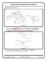
Страница 10: ... to rail by welding as shown Figure 8 NOTE Optional 12 or 24 bolt on sub frame extensions can be installed to convert the 9 subframe to a 10 or 11 as required For optional 45 dump angle applications refer to the 45 Application Sub frame Modification section Hoist Sub frame Installation 1 Position the assembled hoist sub frame onto the truck frame using the application chart shown in Figure 9 Figur...

Страница 11: ...itioned under the mounting angle and the rear hinge angle to clear rivets on the truck frame Welding oxy fuel cutting or grinding sparks can cause fuel to ignite which in turn can lead to injury or death Always take adequate steps to avoid ignition of fuel from fuel tanks when welding grinding or oxy fuel cutting during equipment installation Heat from the truck s exhaust system can cause hydrauli...

Страница 12: ... diameter holes and bolting the mounting angles to the truck frame using two 1 2 GR8 bolts and nuts Figure 11 4 Weld each mounting angle to the sub frame rail keeping within the guidelines shown in Figure 11 Do not weld the mounting angles to the chassis frame 5 Next weld the rear hinge angle to the chassis frame as shown in Figure 12 6 Cut any excess frame off behind the sub frame rear hinge Figu...

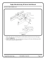
Страница 13: ... Manufacturing SR Series Hoist Manual 7 Slide a lock collar onto each lifting shaft and then slide the shafts into each end of the upper hoist tube Figure 13 8 Install a body guide plate onto each sub frame rail using one of the sets of bolt holes provided Fasten guides using the supplied hardware Figure 13 ...

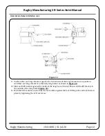
Страница 14: ...de of the long beams Once in position weld the rear hinge brackets to the body long beams as shown in Figure 14 10 Slide each lift bracket against the inside of the long beam channel Then weld the lift bracket to the outside of the long beam Figure 14 11 With the lift bracket secured slide the lock collars against the hoist lifting tube and lock them in place by tightening the 3 8 set screw Figure...

Страница 15: ... Sub frame Installation cont Rugby Manufacturing 1841488C 13 Jul 20 Page 13 101010P1010101101010 Rugby Manufacturing SR Series Hoist Manual Figure 15 12 Install and grease the fittings as shown in Figure 15 ...

Страница 16: ...ation 1867517 EXTENSION 45 DEGREE SF MOD PCBLK 2 Locate the Ø 1 8 x 1 1 2 slot found on the left and right sub frame channels 3 Cut through the left and right sub frame channels at the cut centerline as shown in Figure 16 4 Insert an extension between the front and rear portion of the sub frame rails and install the 1 2 hardware 5 Cut off the excess from the front of the sub frame channels as appl...

Страница 17: ...g ob structions Two Danger decals are supplied with each SR series hoist These decals must be positioned as shown in Figure 18 on both the left and right hand sides of the truck The chosen decal locations should be free of any viewing obstructions To obtain replacement decals contact your Rugby dealer or Rugby Manufacturing Co Missing or damaged decals can lead to accidents which may cause serious...

Страница 18: ... reverse the above procedure The body prop is only to be used to prop an unloaded body Seri ous injury or death can occur if the body prop is misused Maintenance Grease all hoist and rear hinge grease fittings every 100 cycles or every two months Some grease fittings are in hard to find locations Refer to Figure 15 for all grease fitting locations Check hardware regularly and retighten as needed R...

Страница 19: ... 1577459 BOLT 1 2 13 X 1 1 2 FLG GR5 4 20 1576016 NUT 1 2 13 FLANGE GR5 STL PLT 4 21 1535863 1851733 KIT SUB FRAME EXTENSION OPTIONAL 1 ITEM PART DESCRIPTION QTY 1 2117068 FRAME SR 4020 PCBLK HOIST 1 2 1315043 CYLINDER 5 5 X 20 HR 550 1 3 2193587 SUBFRAME 09 SR 4020 1 4 1839407 PROP BODY PCBLK 1 5 1653917 PIN 1 8 X 1 COTTER 1 6 1857937 PIN 1 2 X 2 75 ZP CLEVIS 1 7 1822289 BRACKET SR LIFT 2 8 16538...

Страница 20: ... CYL PINNING 1 8 1653921 COTTER PIN 5 16 X 3 1 2 PLATED 2 9 1844097 SUBFRAME 09 SR 5020 PCBLK 1 10 1822332 SHAFT SADDLE PIVOT 1 11 1653835 HHC SCREW 1 2 13 X 4 GR5 PLT 2 12 1642984 NUT 1 2 13 NYLOCK NE GR8 STL 2 13 1839407 PROP BODY PCBLK 1 14 1857937 PIN 1 2 X 2 75 ZP CLEVIS 1 15 1653917 PIN 1 8 X 1 PLATED COTTER 1 16 1822289 BRACKET SR LIFT 2 17 1656191 LOCK COLLAR 2 25 2 18 1653845 SET SCREW 3 ...

Отзывы: